Single-Phase Induction Machines
Single phase induction motors generally have a construction similar to that of a three phase motor: an ac windings is placed on the stator, short-circuited conductors are placed in a cylindrical rotor. The significant difference is, of-course, that there is only a single phase supply to the stator.
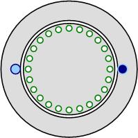
Consider the motor schematic shown in Fig. 1. If an ac supply is connected to the stator winding, a pulsating flux density will be produced, which will link the rotor circuits. The voltage induced in the rotor circuits will cause a current to flow, producing a flux density to oppose change in the stator flux linking the circuit. In the diagram above, both the stator and rotor flux densities will act in the y-direction. i.e. the cross product of flux densities will be zero, the motor produces no torque. This simple qualitative analysis indicates a problem, single phase supplies produce pulsating fields, not rotating fields and pulsating fields do not produce torque. However, single phase motors can be made, so there seems to be a contradiction in what we know works, vs. the analysis.
Double Revolving Field Approach
The double revolving field approach decomposes a puslating magnetic field into two counter-rotating magnetic fields. Consider the equation for a spatially sinusoidally distributed mmf with a pulsating magnitude,
The product of the cosine and sine functions can be expanded to give:
In the above equation, the red section \( \cos\left(\frac{p}{2}\theta_m - \omega_e t \right)\) is a forwards (counter-clockwise) rotating, sinusoidally distributed mmf. The blue section \(\cos\left(\frac{p}{2}\theta_m + \omega_e t \right) \) is a backwards (clockwise) rotating, sinusoidally distributed mmf. This idea is animated in Fig. 2.
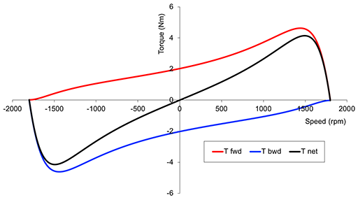
Applying double revolving field theory, it is possible to think of a single phase induction machine as the sum of two smaller induction machines, each trying to rotate in opposite directions. The torque speed curve for a single phase induction machine can be sketched as the sum of two torque speed curves - one tying to drive the machine in the forward dirction, one trying to drive the machine backwards. This idea is shown in Fig. 3.
It can be seen that if there are two equal and opposing rotating fields, then the net torque at standstill will be zero. This is the case considered in the qualitative analysis shown earlier. Considering the torque curves, if a single-phase induction motor can be made to start, a torque is created and the machine will operate as a motor.
Starting
There are a number of different types of single phase induction machine, which have slightly different approaches to creating a rotating field at starting. The majority of single phase indcution machines work by applying two phase currents to the motor (two windings connected to the same supply voltage, with different impedences to create different phase angles for the currents). In the illustration in Fig. 4, there are two phases supplying the motor. If the phase supplies are balanced (the same per-unit mmf), with a 90° electrical phase angle between the currents and a 90° electrical space angle between the coils, then the result is a purely rotational field with no pulsations. If the supplies are unbalanced, or the phase angle is not exactly 90°, there will be a combination of a pulsating and rotating effect. This can be seen in the animation in Fig. 4.
Using knowledge of three-phase induction machines, we know that the impedance of a winding is a function of slip. This adds additional complexity if two balanced winding currents are to be obtained from a single phase supply - the power factor of the winding changes with slip.
Ideally, we want the current in an "auxiliary winding" to lead the main winding current, and we can use a capacitor to acheive this. But, the capacitance required to creates the ideal current phase shift will be different at every slip value. We have to choose capacitance values that either optimally balance the magnetic fields at a given speed (e.g. starting or at the rated load) or a capacitance that gives a compromise between starting and running performance.
Capacitor Start - Capacitor Run Motors
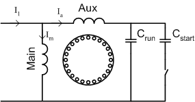
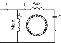
The schematic diagram above shows a main and auxiliary winding placed with a 90° separation around the rotor. There are two parallel capacitors in series with the auxiliary winding. When starting, the total capacitance is given by
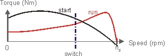
Once the rotor reaches a predetermined speed, the switch will open, and only the run capacitance will be used. This type of switching is obtained using a mechanical spring-loaded centrifugal switch. The combined-torque speed curve for a capacitor start-capacitor run motor is shown below.
Capacitor Start Motor
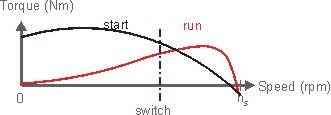
The primary disadvantage of a capacitor start - capacitor run motor is cost. There are two capacitors and a switch. The combined costs of these components and their manufacture is significant when compared to the rest of the motor. If high starting torque is required, but lower efficiency run operation is acceptable, the run capacitor can be eliminated, as shown below.
In this case, the run torque is negative at synchronous speed, due to the backwards rotating field. The backwards field will also introduce torque pulsations and vibration. The combined steady-state torque-speed curve is shown below.
Permanent-Split Capacitor Motor
If run efficiency and vibration are important, but start torque can be compromised, the capacitor can be left in the auxiliary circuit at all speeds. Sizing the capacitor to provide balance at a particular load point, the backwards field can be eliminated, improving efficiency and eliminating torque pulsations.
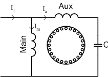
Eliminating the centrifugal switch can reduce the manufacturing cost significantly. The trade-off is lower starting torque, since the capacitor is not sized to provide balance at starting, but for run conditions

Split - Phase Motor
A split-phase motor has no capacitance in the auxiliary circuit. A phase shift with respect to the main current is achieved by using narrow conductors to achieve a high resistance to reactance ratio. Increasing the resistance means that the auxiliary winding can only be used during starting, otherwise, it would overheat.
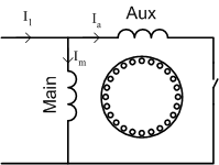
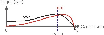
A split-phase motor has significantly lower torque at starting than any of the capacitor motors due to the reduced phase angle between main and auxiliary winding currents.
Summary
Each of the motor types above has different characteristics, but at different costs - capacitors are an increasd expense, as are centrifugal switches; switches may require maintenance. In reality many decisions on which performance is required is based on a trade off of running efficiency and capital cost, as long as the design is capable of bringing the load up to speed.
Shaded Pole Motors
One class of single phase induction motor that is cheaper than any of the two winding (or "split-phase") designs is the shaded pole motor. Typically these motors are used in small sizes, and the most familiar application where you may see a shaded pole motor is a bathroom fan.
A diagram of a simple shaded pole motor is shown in Fig. 13.
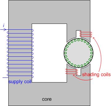
In a shaded pole motor, the rotor is placed in a simple c-core. Half of each pole is covered by a "shading" coil. When an ac current passes through the supply coil, a pulsating flux is produced. As the flux through the shading coil changes, a voltage and current are induced in the shading coil, acting to oppose the change in the flux from the supply coil. As a result, the flux under the shading coil lags the flux in the rest of the coil. The net effect is to produce a small rotation in the flux through the rotor, causing the rotor to rotate.
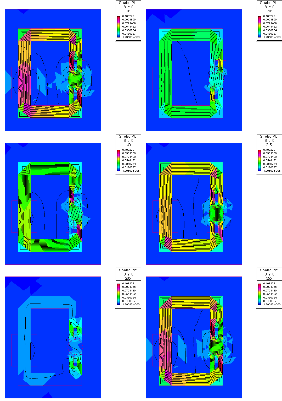
This effect is shown in the flux lines obtained using finite element analysis, plotted in the animation in Fig. 14
