Switched Reluctance (SR) Motors
SR motors are special type of variable reluctance motor designed for continuous operation. Properly designed SR motors are capable of high torques with low weight, making them attractive for vehicle and aerospace applications. The machines are structurally simple but can need relatively advanced control for optimum performance.
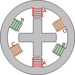
A diagram of a switched reluctance motor is shown in Fig.1. An important point can be seen in the motor diagram.
- The number of rotor poles, \(p_r\) (4 in this case) is different from the total number of stator poles \((p_s\) (6) and the number of poles for a phase
This design is known as a 6-4 SR motor, and operates with 3 phases.
Operation
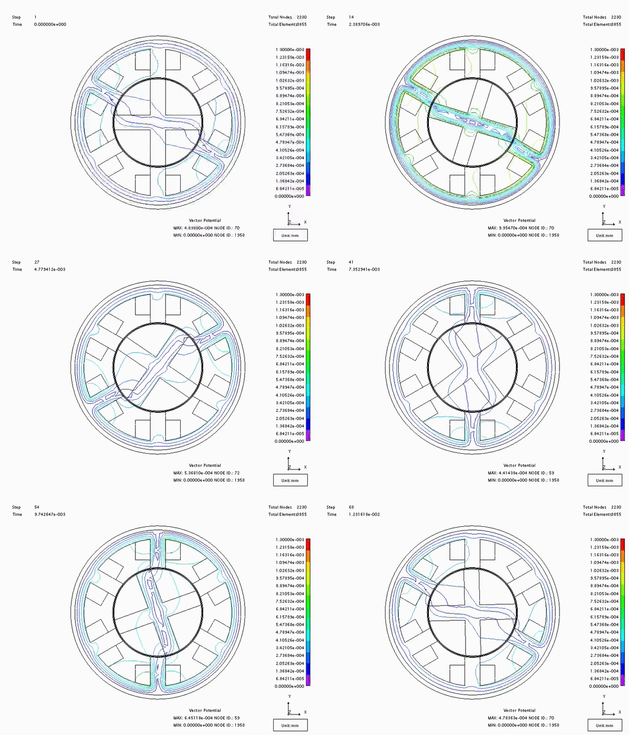
Consider the motor design above. In the position shown, phase B will be excited. The magnetic field created by coil B will cause the rotor to rotate clockwise until two of the rotor poles align with the phase B poles. At this time, phase B can be de-energized and phase C turned on. The rotor will continue to rotate until it aligns with coil C. It should be noted that the magnetic field created by the stator is travelling counter-clockwise, but the rotor moves in a clockwise direction. An animation of the field increasing and collapsing is shown in Fig. 2.
Calculation of power and torque can be carried out by considering the energy stored in the magnetic field, and the approach differs, depending on wether the operation can be considered as using linear magnetic system or a saturating nonlinear magnetic material.
Linear Analysis
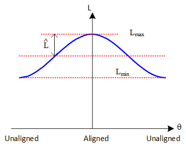
Assuming that the motor doesn't saturate, linear analysis using inductance to find the stored energy is possible. Considering one coil, the inductance will vary approximately sinusoidally with position, as shown in Fig. 3. The inductance variation is periodic, depening on the number of rotor poles \(p_r\).
The inductance can be written as:
If the coil is conducting current \(i\) then the energy stored in the magnetic field is given by
Using the definition of torque as
gives
Torque can be plotted as shown in Fig. 4. Note that the torque waveform repeats \(p_r\) times every rotation, due to the symmetry of the rotor.
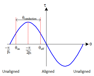
If the machine has \(N_p\) phases, then each phase will conduct for \(1/N_p\) of the periodic rotation angle of \(2\pi/p_r\). Each stator coil conducts for a period of
The peak torque occurs when the rotor pole is \(\pi/2p_r\) away from the rotor pole. For the torque when one phase is turned on to equal the torque when the previous phase is turned off, the turn-on and turn-off torques should be equal. Therefore each coil should conduct for an angle that is symmetric about the peak torque position. The current though a coil should be turned on when the rotor is at a position
and stop conducting at angle
relative to each pole.
\(\theta_{conduction}\), \(\theta_{on}\), \(\theta_{off}\) are angles in mechanical radians and can also be quoted in mechanical degrees.
For the case of a 3-phase 6-4 SR motor, \(\theta_{conduction}=30^\circ\), \(\theta_{on}=-37.5^\circ\) and \(\theta_{off}=-7.5^\circ\).
The average torque can be found by integrating the torque over the conduction period
Nonlinear Analysis
Unfortunately, many real machines operate in saturation and analysis of energy stored using inductance is invalid. In this case, it is important to consider energy as the integral of current with respect to flux:
In SR motor operation there are three distinct steps during a current cycle:
- Current is turned on instantaneously (with no movement)
- Current is held constant while the rotor moves
- Current is switched off instantaneously (no movement)
These three stages are represent on the flux-current plot in Fig. 4.
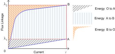
In a plot of flux vs current, the integral for energy is given by the area to the left of the flux-current plot. The integrals for the three distinct steps are shaded on the diagram.
- Current increases from 0 to \(i_1\), unsaturated, and flux increases to \(\lambda_1\)
- Current is constant at \(i_1\). As the rotor moves into alignment, the flux linkage increases to \(\lambda_2\), and the iron in the machine becomes saturated.
- Current is switched off. The stored energy from point \( \left(i_2, \lambda_2\right) \) is returned to the supply.
Net energy can be found from
Where the energy at each step is calculated using
Note that in step 3, the integral will result in a negative value for \(W_3\) as energy is returned to the supply. The total energy is equal to the area enclosed by the flux-current loop; a machine with a large enclosed area transfers more energy in a given switching cycle.
Averge torque over one conducting period is given by
Power can be found from energy transfer over the time of the cycle.
Linearised approach
The nonlinear flux-current plot is often approximated as being made up from 4 straight lines as shown below. This makes calculation of the stored energy much simpler.
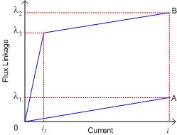
In Fig. 5,