Single Phase Induction Motor Circuit Model
The steady state model for a single winding of a single phase induction motor is developed in this section. It should be noted that the steady state circuit model does not include effects such as pulsating torques. It also doesn't apply to the case where a split-phase winding is used (with or without capacitors). In that case, the backwards rotating field may be completely or partially eliminated.
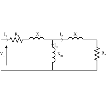
Assuming a single-phase single-winding motor, the equivalent circuit at standstill may be drawn as

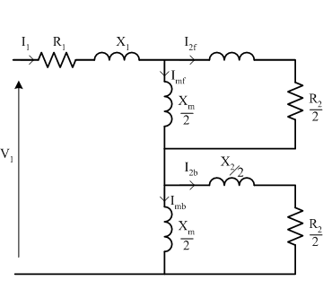
Note that this circuit is identical to the the per-phase circuit of a multi-phase induction machine at standstill. Now, assuming that the pulsating field in the motor can be described using forwards and backwards rotating fields, the standstill circuit can be modified as shown below.

In the diagram shown above, the total impedance is equal to the original circuit, but the magnetising and rotor branches have been divided into two equal components, with forwards and backwards currents to represent the forwards and backwards magnetic fields.
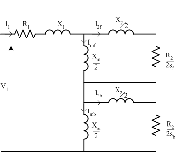
Now, if the rotor rotates, the equivalent rotor resistance in each of the forwards and backwards circuits will be divided by slip, relative to the forwards or backwards rotating field.

In the final circuit, shown above, forwards slip is shown as \(s_f\) and backwards slip is shown as \(s_b\). These slips are defined as
Using the same notation for forward slip as used in three-phase machines:
Analyzing the circuit, rather than solve for the currents in the various parallel paths, it is easier to think in terms of impedances of the different parts of the circuit and the power flow into each part of the circuit. Using this approach it is possible to write the phase input impedance is given as
Considering the circuit and remembering that air gap power is defined as the input power minus the power losses in the stator, the air gap power can be defined using
When considering the torque components, it is important to remember that the forwards and backwards torques correspond to positive and negative synchronous speeds. Using knowledge from three-phase machines, torque is given by airgap power divided by synchronous speed:
The power converted to the mechanical system is calculated by multplyig torque by speed in mechanical radians per second:
The losses in the rotor circuits can be found from the difference between airgap power and output power. Note above that the backwards component contributes to airgap power but acts against output power.
Finally, the output power available on the shaft is given by the mechanical power converter minus the rotational losses.
Points to note
- The air gap power is the sum of both forwards and backwards components.
- If the motor is rotating in the forwards direction, the backwards field is in the braking or plugging region and the rotor copper losses will be higher than the backwards air gap power. (Power flows into the rotor from both the stator and the backwards torque component)
Example
A 2-pole, 120V, 50hz, single-phase induction motor is running at 3420 rpm. The equivalent circuit parameters are:
R1 = 3.5Ω, R2 = 3.2Ω, X1 = 4.1Ω, X2 = 4.1Ω, Xm = 80Ω, Prot = 42.5W
Calculate the input current, input power, power factor, output power and efficiency
Solution
This is a 2-pole 60hz motor, therefore synchronous speed and forwards slip are given by
To find current, first find phase impedance
Input current can be found as
The power factor can be found from the anlge of the input impedance; given by \(\cos(44.3); \color{red}{\text{pf}=0.717\text{lagging}}\)
Remebering that this is a single phase system:
To find output power:
Therefore efficiency is given by
Summary
The equivalent circuit model for a single phase induction machine with only one winding is developed. The airgap power and torque equations are developed in terms of a backwards rotating field theory. Note that as in the example, the efficiency and power factor of single phase machines is typically low, relative to three-phase machines. The low efficiency is due to the additional losses due to the backwards field, the low power factor because reactive poewr is required to support the backwards field.