Stepper Motors
Stepper motors are part of a class of motor called variable reluctance motors. Operation of this type of motor does not necessarily require two excitation sources. Movement occurs due to magnetic attraction between field sources and magnetic materials. (e.g. the force that occurs when a magnet is placed close to a piece of steel)
This effect is illustrated in the simple diagram below. A simple piece of steel is free to rotate between two poles, which are driving flux through the stator.
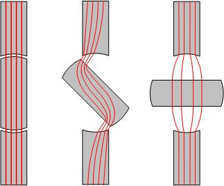
In the diagram on the left, the rotor and stationary poles are aligned. In this case there is no torque applied to the rotor as the rotor may move small displacements without affecting the energy stored in the magnetic field. In the diagram on the right, the rotor is completely misaligned, but again, a small displacement will not affect the energy stored in the magnetic field and the net torque is zero. In the centre diagram, the rotor is displaced by 45°. In this case, the maximum torque is applied to the rotor as there is large rate of change of energy with position. Mathematically, torque is related to energy stored using
Reluctance Stepper
A reluctance stepper motor has only stator excitation, there is no rotor field. A simplified layout of a stepper motor with 6 phases and a two pole rotor is shown below.
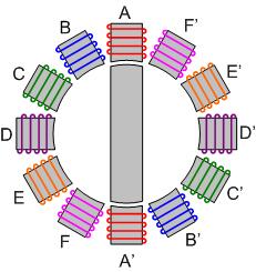
Operation of this type of stepper motor is relatively simple:
- Excite winding A, the rotor moves to align with A-A'
- Excite winding B, the rotor moves to align with B-B'
- Continue stepping through phases at desired rate for desired speed, or until desired position is reached
Stepper motors are excellent for low torque operation where precise precision control is needed, together with the ability to rotate forwards and backwards as needed. Typical uses include robotics and other servo-motor applications.
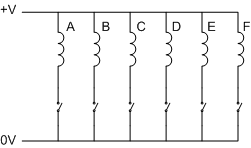
One advantage of reluctance stepper motors is that they only require very simple power supplies. In the case of a 6 phase motor shown above, only 6 switches (probably MOSFETS) are needed, as shown below.
Permanent Magnet Stepper
The torque density (torque per unit volume) of a stepper motor can be increased by adding a permanent magnet to the rotor. The permanent magnet increases the flux density in the air gap (thereby increasing the stored energy and rate of change of stored energy with position). An example diagram for a permanent magnet stepper is shown below.
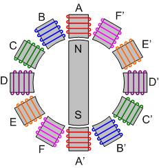
As a permanent magnet stepper motor rotates, each pole of the stator must be capable of producing either a north or south magnetic pole, depending on the position of the rotor. This is different from the case of the reluctance stepper, where the direction of the flux is not important. As a result, the coils in the stator winding must be able to take bi-directional currents, increasing the supply complexity. An example of a possible supply that only requires twice as many power electronic switches (but needs a split DC supply) is shown below. (It is also possible to supply each phase with a H-bridge converter, requiring significantly more switches)
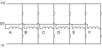
It should be clear that the primary disadvantage of a PM stepper compared to a reluctance stepper will be cost. The additional cost of magnet material plus drive complexity is relatively large. There are two advantages of using permanent magnets:
- increased torque capability
- holding torque
Holding torque occurs when the supply is switched off. In a PM machine, the magnets will provide enough torque to prevent the rotor from rotating.