AC Circuits Review
AC notation
Voltage and currents in ac systems are usually assumed to be sinusoidal. In single phase power systems the voltages in the system can be described as
where \(\psi\) is the phase angle of the voltage and \(\omega_e\) is the angular electrical frequency. \(\vec{V}\) is a phasor defined in terms of the rms voltage. Unlike other areas (e.g. signal processing, communications) phasors in power systems are always defined in terms of rms magnitude, not peak magnitude. The rms of a sinusoidal quantity is given by
and the phasor notation is
In single phase systems \(\psi_v\) is often set to zero and voltage phase angle is used as the reference for the rest of the system. Defining \(\psi_v = 0\) the voltage and current in a single phase circuits are written as
Where \(\theta\) is the electrical angle between the voltage and current. In power systems, which are usually inductive, \(\theta\) is usually negative.
Single Phase Power
Power flow in a system is the rate of change of energy past the point in the system where voltage and current are measured. Instantaneous power is the product of the voltage and current functions of time:
The interactive graph plots example voltage, current and power waveforms as functions of \(\omega_e t\).
From the above equation and plots, it can be seen that the power is comprised of two components, a steady value and a component oscillating at twice the supply frequency. It can also be seen that at certain points, the instantaneous power is negative. Negative power indicates that energy flow is in the opposite direction to the defined direction of positive current flow. To obtain the average power flow with time, it is necessary to integrate power over one supply cycle:
Reactive and Apparent Power
It should be clear that there is a current flow and instantaneous power flow which is not associated with actual power transfer. This occurs when a circuit contains energy storage components including capacitors and inductors. With these components, energy is transferred back and forth between the system and the component each cycle, with no net power transfer. To quantify the current and energy flow due to these component use the terms Apparent Power or Voltamperes, denoted using \(S\), Reactive Power or Voltamperes-Reactive \(Q\), and power factor. Complex Voltamperes are defined using them product of the voltage phasor and complex conjugate of the current phasor:
\(S\), the magnitude of \(\vec{S}\), is the magnitude of the oscillating component of instantaneous power with units of VA, and Q is proportional to the energy stored in the system, with units of VAR. (Note that Watts are reserved for real power flow). The relationship between Voltamperes and power is given by the power factor:
The cosine of the angle between voltage and current is sometimes called displacement power factor (DPF) or fundamental power factor (FPF). In a system with only fundamental current, the power factor equals the displacement power factor.
Three Phase Power Review
In a three phase power system there are three circuits and the voltages and currents in each of the circuits are phase shifted by 120° electrically, from the voltages and currents in the other two circuits.
The phase voltages in a circuit may be written in time notation as
where the subscript \(\phi\) is used to identify that this is a phase voltage.
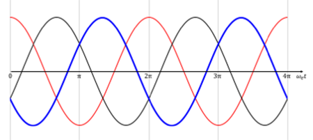
Writing the voltages as phasors (using electrial degrees this time, rather than radians):
If we assume a balanced system (impedances and induced voltages of each phase branch are equal), the currents may be written as
Three-phase Circuit Connections
Up to this point the three phase system has been defined in terms of the individual phase legs of a load or supply (a, b or c). The power system line quantities can be found from the phase quantities, depending on the circuit configuration. There are two types of common three-phase connection, Y- and Δ. The relationship between component phase quantiities and supply line quantities can found mathematically graphically. In the system supplying the load, consider three lines (1,2,3) with
- line-line voltages \(V_{12}\, V_{23}\, V_{31}\)
- \line currents \(I_{1}\, I_{2}\, I_{3}\)
From the supply line variables (shown in blue in the diagrams below), it is impossible to know if the system is connected to a Y- or Δ- circuit (shown red)
Y-Connection
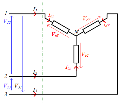
From the circuit diagram it can be seen that
The voltage phasor relationships are plotted graphically in Fig. 4.
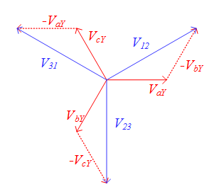
Considering \(V_{12}\) the line-line voltage is given in terms of the phase voltage by
The rms line-line voltage and rms line current are defined in terms of the rms phase quantities as:
Δ-Connection
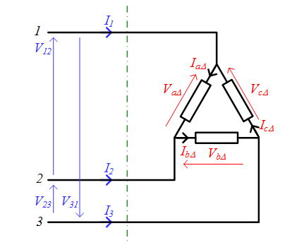
From the circuit diagram it can be seen that
The current phasor relationships are plotted graphically in Fig. 6.
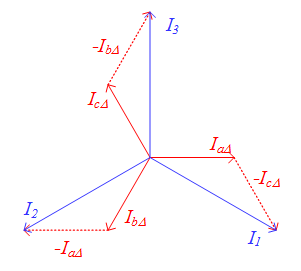
Considering \(I_{1}\) the line current is given in terms of the phase currents by
The rms line-line voltage and rms line current are defined in terms of the rms phase quantities as:
Thee-Phase Power Flow
Instantaneous power flow in each leg of the load is the product of instantaneous voltage and current:
and the total power flow can be found from the sum of the power in each leg. In balanced systems, the total power is constant as the oscillating components cancel,
i.e. in balanced three-phase systems the total power is three times the average power in one of the phases. Apparent and reactive power are given by
Power flow in a three phase system can be defined in terms of either phase or line quantities:
Summary
This page re-caps the basics of ac single phase and three phase power, reactive power and apparent power calcualtions. Importantly, the notations for time-varying signals, RMS, peak and phasors are introduced. This notations is used in the rest of the ac material on this site.