Field Winding Connections
Up to now we have considered the induced voltage and torque produecd by an armature coil, assuming the presence of some flux \(\phi\) whithout considering the source of the flux. The armature circuit behaviour is dependent on the flux in machine. Traditionally the flux is produced and controlled by a field winding. Many modern DC machines are constructed with a permanent magnet (PM) field, which results in a constant flux. In a PM DC machine, the armature circuit model is the complete circuit model, and \(k\phi\) is constant. We will consider three basic types of DC machine where the operation is dependent on a field winding:
- Separately Excited
- Shunt Excited
- Series Excited
Separately Excited
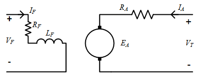
In a separately excited machine the field winding is independent of the armature winding. The armature and field winding voltage loop equations are
The field circuit resistance \(R_F\) may be made up of the actual winding resistance, \(R_{field}\) and a variable resistance, \(R_{adj}\) which can be used to control the field current. The field circuit can aslo be controlled by adjusting the field current
The flux produced by the field winding is a nonlinear function of current:
At lower current levels, the flux-current relationship is linear, but as the current increases, the iron in the machine starts to saturate. The field current (and hence flux) can be controlled by either adjusting the field circuit resistance or the field supply voltage.
For a separately excited machine, the armature current equals the armature terminal current.

Shunt Excited
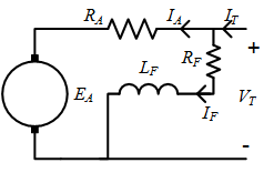
A shunt excited machine is essentially the same as a separately excited machine, with the constraint that the field winding supply voltage \(V_F\) is equal to the armature winding supply voltage, \(V_T\). In this case the terminal current is given by
In this case the field current can only be independently controlled using an adjustable resistance in the field circuit.

Torque-Speed Characteristics for Shunt and Seperately Excited Machines
The field current, and therefore flux, can be controlled independenty of speed and terminal voltage for both shunt and seperately excited dc machines. (Shunt excited machines have a smaller range of adjustment than seperately excited machines.) Therefore, the torque-speed characterisitcs of these two types of machines are similar. Substituting the armature voltage and torque equations
into the armature loop voltage equation gives:
Re-arranging, the relationship between torque and speed for both separately excited and shunt excited machines is obtained:
Analyzing the torque speed equation, is becomes apparent that the field of a separately excited machine should always be turned on before a voltage is applied to the armature circuit. If the field current and flux are zero, the machine will theoretically accelerate to infinite speed. In reality, there is always some small residual flux in the machine: the induced back emf will be very small, resulting in very high armature currents; torque will be produced, due to the high currents and small residual flux; eventually friction will limit the speed, but damage is likely to occur to the motor either from over-speed or over-temperature due to armature \(I^2R\) losses. The characterisitic of relatively consant speed, with a small speed reduction as the load increases historically made this type of machine attractive for applications such as fans and pumps.
Series Field Connection
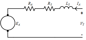
The equivalent circuit model for a dc machine with a series connected field winding is shown above. To indicate that the field winding is connected in series, the series field resistance is labelled \(R_S\). In a series connected machine, the armature, field and terminal currents are equal:
As the armature current of a machine is typically much higher than the field current of a separately excited machine, the field winding in a series machine has fewer turns than the field winding in a separately excited machine. (Remember that mmf is the number of turns multiplied by current). The series resistance \(R_S\) is therefore typically much smaller than \(R_{field}\). In addition, the flux level in series motors can often assumed to be lower, with a linear relationship between flux and current.
can be replaced by
where \(c\) is a constant. This linear relationship can substituted for flux in the armature voltage equation and the torque equation.

Analyzing the circuit:
The armature voltage equation and torque equation, together with the linear relationship for flux, can be substituted into the series armature loop voltage equation to obtain and understanding of the relationship between speed, current and torque at as a function of terminal voltage.
Considering these equations gives some intuitive qualitative understanding of the relationship between speed and torque. If the speed is low, then the current will be high. If the current is high, then the torque will be very high. If the torque is low, current will be very low, and speed will be very high. Re-arranging gives torque-speed relationship for a series machine
This relationship is plotted in Fig. 5. From the plot and equation it can be seen that a voltage should not be applied to a series motor unless a torque is applied. If the torque is zero, the rotor speed will theoretically increase to infinity. The characteristic of very high torque at low speed and high speed at low torque makes series motors a good choice for applications that include traction and power tools.
Summary
The armature circuit for a DC machine and three circuit connections for the armature and field circuits, a shunt connected, separately excited, and series excited are presented. The torque-speed relationships, for each type of machine are derived.
This page also introduces the concept of equivalent circuit models. These are simple lumped parameter models that describe the operation of an electric machine. These are generally good simple models of the operation of electrical machines in steady state under normal operating conditions and this approach is used throughout the coures.