Example
A three-phase six pole 60Hz generator is designed with "2 slots per pole per phase".
- How many slots are required
- How many coils are there per phase?
- If the rotor produces a flux density \(B=1.0\cos(\omega_e t -3\theta_m)\), there are 10 turns per coil and the
dimensions are: stator inside radius \(r=0.5m\), stator axial length \(l=1.0m\)
- What is the rms induced voltage in one coil?
- What is the total voltage induced in one phase, if all coils are connected in series?
Solution
- There are six poles and three phases, so 2 slots per pole per phase requires 2×3×6 =36 slots
- Each coil requires two slots (one for each side of the coil). In a single layer winding (which is all you need to know about in this course) 36 slots will be filled by 18 coils. There are three phases, so each phase will have 6 coils.
-
Now, to find the voltage in a coil or a phase, we can use the formula
\[ E = \frac{1}{\surd 2} \omega_e \hat{\lambda}_{ph} \]For a single coil in a multi-pole machine
\[ \begin{aligned} \lambda_{coil} & = N_t r l \int_{\beta}^{\beta+\gamma} \hat{B} \cos\left(\omega_e t - \frac{p}{2}\theta_m\right) d\theta_m \\ \lambda_{coil} & = 2 N_t r l \frac{2}{p} \hat{B} \sin\left(\omega_e t -\frac{p}{2}\beta \right) \\ \hat{\lambda}_{coil} & = 2 N_t r l \frac{2}{p} \hat{B} \end{aligned} \]For the specific case in this example
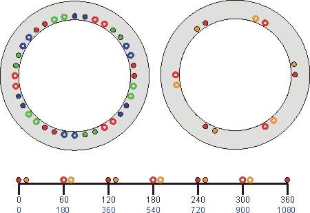
\[ \begin{aligned} \hat{\lambda}_{coil} & = 2 \times 10 \times 0.5 \times 1.0 \frac{2}{6} 1.0 \\ \hat{\lambda}_{coil} & = 3.33 \\ E_{coil} & = 2 \pi 60 \frac{3.33}{\surd 2} \\ E_{coil} & = 888V \end{aligned} \] All three red coils are electricall 360° apart, so their voltages will be in phase with each other. Similarly, all three orange coils will be in phase with each other. The orange coils are 10° mechanically from the red coils, or \(10\frac{p}{2}=30\)° apart electrically. From the derivation above, if the coil is at angle +30° then the voltage will lag, with phase angle -30°. Therefore the total phase voltage is given by:
\[ \begin{aligned} \vec{E}_{phase} & = 3E_{coil}\angle 0^{\circ} + 3E_{coil}\angle -30^{\circ} \\ E_{phase} & = 3E_{coil} \left| 1+1\angle -30^{\circ} \right| \\ E_{phase} & = 3E_{coil} \left| 1+\frac{\surd 3}{2} -j 0.5 \right| \\ E_{phase} & = 5150V \end{aligned} \]
The basic location of the coils in the machine is shown in the diagram below. The diagram on the left shows the location of all 18 coils, for phases coloured red, green and blue. The diagram on the right shows the coils for only one of the phases, with two colours to indicate the different coils. The coils are physically separated by 10 mechanical degrees, which for a 6 pole machine equals 30 electrical degrees. The scale at the bottom shows that all the red coils are at the same electrical angle (multiples of 360 degrees), while all the orange coils are 30 electrical degrees from the red coils. As a sinusoidal flux of electrical period 360 degrees moves past the coils, the voltages in the red coils will be in phase. The voltages in the orange coils will be offset by 30 electrical degrees.

Consider just the red coils for the time being. There are 3 coils that will have induced voltages in phase with each other. Mechanically, the coils can be thought of as being located as follows:
| Coil # | Start Angle, \(\beta\) | Return Angle, \(\beta + \gamma\) |
|---|---|---|
| 1 | 0° | 60° |
| 2 | 120° | 180° |
| 3 | 240° | 300° |