Towards a DC Machine
In the basic machines material it was shown that rotating a pair of conductors in a constant magnetic field will produce an induced sinusoidal voltage. The electromagnetism review also showed how it is possible to create a constant magnetic field using direct current. There are two stages remaining before a dc machine can be produced:
- Produce a steady voltage
- Rectify the voltage to produce a direct, non-alternating, current
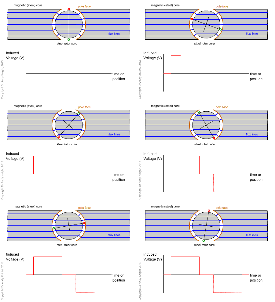
Consider the animation of a basic machine shown below. The structure of the machine is similar to that seen previously, but with some important modifications to direct the magnetic flux paths. The coil has now been placed on a rotating steel core, the rotor core, and the stationary steel core stator corehas been constructed with curved pole faces that are concentric with the path traced out by the conductors on the rotor. This creates a uniform distance between the stator and rotor surfaces, we can say that the air gap is constant. Due to the fact that the permeability of steel is much higher than air, we can assume that the flux lines will cross between the stator and rotor in the shortest path, i.e. perpendicular to both the rotor and stator surfaces.

Assume that the magnetic flux flows from left to right. We can see that the flux leaves the steel core section on the left, through the rotor and into the core on the right. Each stator surface acts as a magnetic pole (N-pole on the left S-pole on the right). The flux is said to flow out of the north pole face and into the south pole face.
Summary
This section introduces the terminology of "rotor", "stator", "air gap" and "pole face". The design shows how we can utilize the permeability of steel to direct magnetic fields and create a system where the flux density, conductor motion and conductor alignment are mutually perpendicular.
Voltage and Torque in a Simple Machine
The voltage induced in a loop formed by the conductors in the simple DC machine shown above can be obtained by considering the generator equations and the physical arrangement. The conductors on the rotor surface are arranged so that the conductor direction is perpendicular to both the direction of motion and the flux path. Therefore, when a conductor is under the pole face, it will be passing through a the uniform field at constant speed and the induced voltage will also be constant. If we define the length of the machine to be \(l\), then mathematically,
becomes
and with two conductors in series, the voltage induced in a loop is given by
Note that when we say "elsewhere", the voltage is zero when the conductors are in the small space between the pole faces, where the flux density is also zero. In addition, it is important to note that the flux density in the equations above is defined as the flux density in the air gap. This is not the same as the flux density in the stator or rotor cores, as the cross-section of the flux path changes as the flux moves between stator, air gap and rotor.
Now, if the speed of rotation is defined as \(v=r\omega\) then
In the case of a simple machine, we saw that it can help to define voltage in terms of flux or flux linkage, rather than flux density. To calculate the total flux passing through the loop formed by the conductors, we must consider the flux that crosses the air gap. For a 2-pole machine, if we assume that the gap between the poles is negligible (the gaps at the top and bottom of the diagram) then the surface area of one pole can be written as
And for the simple 2-pole machine the volltge induced in one loop (formed by two conductors) is given by
Torque
To calculate the torque developed when current flows through the conductors, we can consider the case when Now, a positive current flows into the positive voltage terminal and through the loop. This is the case when we have a motor (power flows from the electric circuit into the machine). Remember that torque is the cross product of the vector distance from a pivot with the force applied
and that force is given by
Due to the arrangement of the conductors, perpendicular to the air gap flux density, the torque produced by a single conductor is given by
For 2 conductors we can find the total torque and follow the same procedure as for voltage:
Summary
This section derives the induced voltage in a single coil placed on a magnetic cylyinder, rotating in a system with a constant field and curved pole faces. An expression for the torque due to a current flowing in the same coil is also derived. These equations indicate that it is possible to design the system to produce constant voltage and torque, for the parts of the rotation when the coil is under a pole face.