DC Armature
The armature of an electric machine is the name historically given to the winding where a voltage is induced and power transfer between electrical and mechanical systems occurs. It is a term used in dc machines and ac synchronous machines. In a dc machine, the armature is the rotating circuit.
Commutation
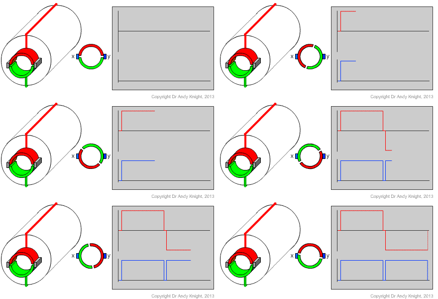
In a DC machine, developed before the era of power electronics, a mechanical system is used to switch the AC generated loop voltage and give a DC voltage at the terminals of the machine. This process is called commutation. The mechanical switching is acheived using a device called a split-ring commutator. Consider the drawing and illustration in Fig. 1. Each conductor (or each side of a loop) is connected to a cylindrical conductor, that is split into two halves. As the rotor rotates, the cylinder is in contact with stationary brushes. (Originally, copper wire bushes were used; modern machines use spring loaded graphite blocks.)
As the rotor rotates, the halves of the split ring commutator move past the stationary brushes. As time progresses, the x and y terminals become connected to alternating ends of the rotor conducting loop
Considering the plots of the induced (red) and terminal (blue) votlages with time, it is clear that the voltage induced in the conducting loop on the rotor continues to alternate between positive and negative. However, because of the positioning of the brushes, the measured voltage at the x-y terminals is uni-directional.

Increased Poles & Conductors
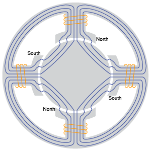
Realistic designs for dc machines usually have more than 2 poles. Increasing the number of poles for a particular flux per pole will increase the induced voltage at a given speed and increase the torque available per amp. Fig. 1 gives an illustration of the layout of a stator with 4 poles. Each pole will carry a coil forming part of a field winding. The flux pattern will be similar to the flux lines shown, alternating north and south poles.

For the general case with \(p\) poles, the field pattern will repeat every \(720/p\) degrees.
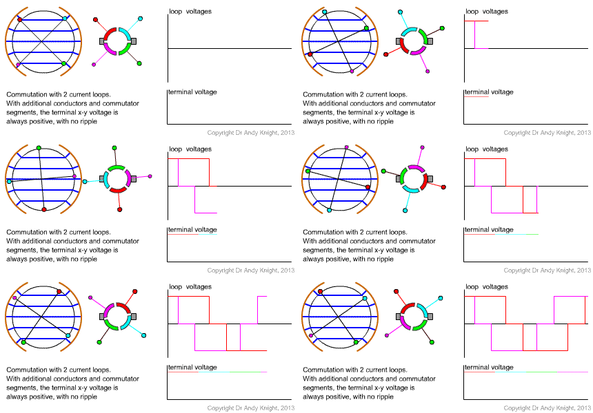
In the original basic machine that has been considered, there are only 2 conductors, or one loop on the rotor. If the number of coils (and split-ring commutator segments) is increased then the brushes can be designed to always be in contact with a conductor that is under the pole face. An example of this idea with two coils is shown in Fig. 3

Equations for a general machine
Each conductor on the rotor of a machine has an average induced voltage given by
\(e_{av}\)is the average induced voltage and \(B_{av}\)is the magnitude of the average flux density under the pole face. Using the general equation for the surface area of a pole
an equation for average voltage induced across a conductor under the pole face can be found in terms of flux and speed:
Now, if instead of a single loop of wire there is a coil with a total of Z conductors (\(Z/2\)turns) connected in series at any one time :
The winding in the machine where the voltage is induced is called an armature winding. In a dc machine, the armature winding is the winding on the rotor. Defining the DC machine constant \(k\):
results in the armature voltage equation.
Similarly to the general voltage derivation, the torque on a single conductor can be written as
which results in the total torque given by the dc machine torque equation.
Note that as we have moved to equations with steady dc values, the armature voltage equation is written in upper case as \(E_A\) to denote that it is a constant voltage, and the torque equation uses \(I_A\) to show that the curent is a constant DC value.
Armature Circuit
Armature Equivalent Circuit Model
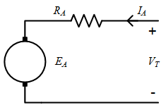
The equivalent circuit model for the armature of a dc machine is shown in Fig. 1. The induced armature voltage, \(E_A\) is represented by a voltage source, connected via 2 brushes to the rest of the circuit. The armature winding resistance is \(R_A\) and terminal voltage is \(V_T\). The armature circuit equation is
Considerig the equivalent circuit model, it can be seen that the measurable voltage of the machine, the terminal voltage \(V_T\) is only equal to the armature induced voltage \(E_A\) when the armature current \(I_A\) is zero. This occurs in two cases:
- no-load: The armature terminals are connected to a voltage source but there is no load torque. In steady state, the motor torque and load torque are equal and opposite, i.e. \(\tau=0\). Therefore the armature current \(I_A\) is zero acccording to the torque equation and \(E_A=V_T\)
- open circuit: This is a testing case when the machine is rotated by an external mechnical system, and the terminals of the machine are open circuit. Again in this case, \(I_A = 0 \), and \(E_A=V_T\)

Summary
This page extends the simple DC equations to a case with mulitple poles and conductors. Two important equations for DC machines are derived:
- The armature voltage equation
- The DC machine torque equations
The armature is modelled using an equivalent circuit that includes the effect of the armature winding resistance.
\(E_A\) is the induced internal armature voltage; \(V_T\) is the terminal voltage.