Determining Induction Machine Parameters
Three tests are needed to determine the parameters in an induction machine model. Detailed testing is quite involved and is specified in IEEE Standard 112.
DC Resistance Test
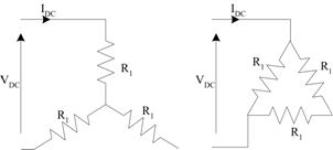
If a DC voltage is applied to the stator terminals, there will be no potential difference across any inductance and no induced voltage on the rotor. As a result, the per-phase circuit is reduced to the stator winding resistance. Applying a DC voltage across two motor terminals and measuring the current, the stator resistance can be found. Considering the figures below, it can be seen that the apparent impedance will depend on whether the machine is wye or delta connected.
Locked Rotor Test
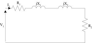
In the locked rotor test, the rotor of the machine is prevented from rotating and the supply voltage gradually increased until rated current is reached. When the rotor is stationary , the slip, \(s=1\) and the equivalent circuit can be drawn as show in Fig. 2.
Analysing the circuit:
Therfore, if the stator power, current and reactive power are measured, the resistance and leakage reactances can be found.
Ideally, the locked rotor test should be performed at a reduced frequency to account for skin depth and more accurately predict the rotor resistance under load conditions. Typically, this test is done at 1/4 rated frequency. With the value of stator resistance from the DC test, the rotor resistance referred to the stator can be found.
If the locked rotor test is done at reduced frequency, then the reactances (which are proportional to frequency) must be scaled to find the correct value at rated frequency:
At this point, only the total leakage reactance is known. The relative values of stator and rotor leakage are defined in the Standard, based on experimental experience. The fractions of reactance as a function of total leakage reactace are given in Table 1.
| Motor Type | \(X_1\) | \(X_2\) |
|---|---|---|
| Wound Rotor | 50% | 50% |
| Class A | 40% | 60% |
| Class B | 40% | 60% |
| Class C | 30% | 70% |
| Class D | 50% | 50% |
No Load Test
The no-load test of an induction machine enables the magnetizing reactance, core loss resistance and friction and windage loss to be calculated. To be able to seperate friction and windage losses from core losses, an adjustable power supply is required. If a fixed voltage power supply is used, the separation of losses is not possible. In this case, the losses may be grouped as "rotational losses". The theory behind this test for both cases is presented.
No Load Test - Core Loss combined with Friction and Windage
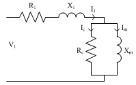
During the no-load test, the machine is allowed to accelerate up to synchronous speed with no load applied. The machine will run close to synchronous speed, with s → 0 If slip approaches zero, the rotor current will fall to zero and the equivalent circuit can be drawn as shown below.
Remembering that this is a per-phase circuit we can write
where rotational losses are defined as
Note that we assume that stray load losses are zero at no-load
Measuring the stator current, power and reactive power, the remaining paramters can be found. Using the power, if stator resistance is known (from the DC test), the total rotational losses can be found
Using the value of \(X_1\) from the locked rotor test, the magnetising reactance, \(X_m\), may be found from the no load reactive power.
No Load Test - Identifying Core Loss and Friction and Windage
Including the core loss resistance,the circuit at locked rotor becomes
In this case, the input power and reactive power are given by:
where \(E\) is the voltage across the magnetizing branch
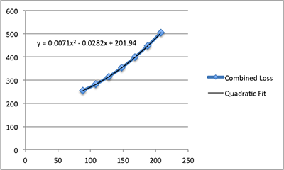
.In order to seperate core loss from friction and windage, it is necessary to measure the input power at as the input voltage is reduced. Subtracting the stator copper loss, the total core loss plus friction and windage may be plotted as a function of supply voltage. Extrapolating to zero volts, when the core loss will be zero, it is possible to estimate the friction and windage. An example of this plot together with a quadratic fit (in this case an automatic trendline from Excel) is shown below. From the data, it is possible to estimate the friction and windage as approximately 200W.
With \(R_1\) and \(X_1\) known, it is possible to calculate \(E\), then find \(R_C\) and \(X_m\) from the input power and reactive power
.