Standards and Legislation
Influence of Rotor Design on Performance
When evaluating the torque speed curve it is clear that the rotor circuit resistance has significant impact on pull-out slip, the speed at which maximum torque occurs. Figure 1 illustrates two cases, with low rotor resistance on the left and high rotor resistance on the right.It can be seen from the plots that a high rotor resistance will provide a high starting torque, leading to rapid acceleration of the mechanical system. This can desirable since during starting the stator current is significantly above the rated current. Short acceleration times reduce the stress on the power system caused by high currents.
While high starting torques are desirable, high rotor resistance results in a relatively high slip during normal running operation. As torque is porportional to rotor joule losses divided by slip, high resistance causes increased losses and reduced efficiency during normal operation.
The above points cause a problem. For most applications it is desirable to have:
- high starting torque
- high efficiency at rated speed
However, designs with high starting torque will have low efficiency at rated speed and designs with high efficiency will have low starting torque. In order to resolve these confilicting requirements, two steps must be considered:
- Careful consideration of the application requirements
- Designs of motors with variable rotor resistance.
Application Requirements
Many motor applications will not need both high start torque and high rated efficiency. Alternately, the requirement for either high start torque or efficiency may be so significant that it over-rides other requirements. Consider two examples:
Fan Load
Fans and rotary pumps typically have a torque requirement that varies as either the square or cube of mechanical speed. When driving a fan, the motor must provide rated torque at rated speed, but at lower speeds the torque demand is significantly lower. A fan application will therefore not usually require significant starting torque, efficiency during steady operation at rated speed is the over-riding concern.
Variable-torque high-inertia loads
This type of load typically includes mechanical punches and reciprocating rod pumps used in oil production. In the case of a reciprocating pump, the mechanical laod varies with time, some of the time the motor is working against gravity to lift oil out of the ground, at other times, it is working with gravity as the rod falls. The speed range of this system is significant, requiring very high torques at low speeds. When the motor is at high speed (as the rod falls) the torque (and efficiency) requirement is minimal. In this case high torque at low speed is the over-riding requirement.
Varirable Rotor Resistance
Although it is common to think of low frequency conductors as having a constant resistance, the resistance of all ac conductors is a function frequency. Induced currents in conductors act to oppose the originating magnetic field. As a result, the depth of penetration of the magnetic field into the conductor will vary with frequency. (The magnitude of the induced voltage is a function of rate of change of flux, and therfore a function of frequency)
Skin Depth
The skin depth of a conductor is defined as the depth at which the magnitude of a magnetic field has fallen to 1/e of the magnitude of the surface. We can approximate this as the depth at which currents are actually flowing in the conductor. Skin depth is given by
where
- \(\delta\) is skin depth
- \(\mu\) is the permeability of the conducting material (\(\mu_0\) for non magnetic metals)
- \(\sigma\) is the conductivity of the conducting material
- \(f\) is the frequency of the magnetic field as seen by the conductor
Since the frequency of the stator magnetic field seen by the rotor conductors is a function of slip, the actively conducting region of the rotor bars will be a function of slip. Hence, the effective rotor resistance will be a function of slip. Table 1 plots skin depth for aluminum, \(\sigma=2.9\times10^7\), in a machine with a 60Hz supply.
The table illustrates a number of important points:
- No matter how deep a rotor bar, only the top 12mm conducts at standstill
- Medium-large machines with bars deeper than 12mm will have varying rotor resistance
- Smaller machines with bars less than 12mm deep will have effectively constant rotor resistance
As an example, a machine with a rectangular bar 72 mm deep will have a resistance 6 times smaller at low slips than it will at starting.
| Slip | Slip Frequency (hz) | δ (mm) |
|---|---|---|
| 0.025 | 1.5 | 76.3 |
| 0.05 | 3.0 | 54.0 |
| 0.083 | 5.0 | 42.8 |
| 0.167 | 10.0 | 29.6 |
| 0.333 | 20.0 | 20.6 |
| 0.50 | 30.0 | 17.1 |
| 0.667 | 40.0 | 14.8 |
| 0.833 | 50.0 | 13.2 |
| 1.0 | 60.0 | 12.0 |
NEMA Motor Design Classes
Since different applications need different characteristics from induction motors, the National Electical Manufacturers Association (NEMA), a US organization, has specified different classes of induction motor, with different characteristics. Typical torque speed-curves for classes A-D are sketched in Fig. 2.
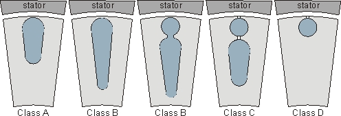
Motor Classes A and D are obtained by designing the rotor resistance to be either low (class A) or high (class D). Classes B and C are obtained by exploiting the effect of skin depth to obtain a variable resistance rotor circuit. Example rotor conductor designs for classes A through D are shown in Fig. 3. Comparing classes A and B, class B has a deeper bar to exploit skin depth effects. The bar width may vary in order to enhance this effect. Class C rotors are typically fabricated with two seperate cages. Only the outer cage will conduct at starting. There is air between the cages and at the top of the slot (to reduce leakage flux). Note that cast rotor designs must have a closed slot design to prevent molten aluminum from escaping. Class D has a small conductor, giving a high resistance at all slips. The class D example shown has an open slot, for a fabricated rotor design.
A summary of the performance of the motor classes is provided in the table below
| Class A | Class B | Class C | Class D | |
|---|---|---|---|---|
| Type | General Purpose | General Purpose | High Starting Torque | Very High Starting Torque |
| Start Torque | 100% rated for larger motors, 200% rated, smaller motors | 100% rated for larger motors, 200% rated, smaller motors | Approx 250% rated | > 275% rated |
| Start Current | ˜800% rated | 500%-600% rated | ||
| Pullout Torque | 200%-300% rated | ≥200% rated | Slightly lower than class A | |
| Pullout Slip | <0.2 | <0.2 | High, can be as much as 1.0 | |
| Rated Slip | <0.05, lower than similar sized class B | must be <0.05, usually <0.03 | <0.05, higher than class B | High, typically 0.07 to 0.11, can be up to 0.17 |
| Applications | Fans, Blowers, Pumps, Machine Tools | As for Class A | Compressors, pumps, conveyors | High inertia applications, e.g. mechanical punches |
| Notes | High starting inrush current causes power system problems, it can cause the supply voltage to sag and requires special starting techniques. More efficient than same sized class B | Replacemesnt for Class A due to lower start current. The standard off-the shelf commodity motor. | Applications that require high start torques. Note that the pullup and pull-out torque can both be lower than the start torque. Less efficienct than class B | Very high inertia applications. e.g. in a punch or reciprocal pump where the slip may vary between 0 and 0.50 Much less efficient than other designs |
History, Efficiency & Standards
History
The induction motor was demonstrated and desctibed in a paper published by Gallileo Ferraris in Turin, Italy, in 1888. At the same time in N. America, the principle was patented by Nikola Tesla, also in 1888. By 1895 three-phase induction motors similar to today's designs were available. Since then induction motors have become smaller and more efficient. These improvements are not necessarily compatible with each other and have occurred for different reasons.
- Smaller machines have been developed because it is in the manufacturers interest to do so. A physically smaller induction machine with the same output capability will have lower material costs and therefore can be made more profitably.
- More efficient machines have been developed because of a combination of end user desire and legislation. More efficient machines will have lower operating costs and require less generation= which results in lower greenhouse gas emissions from fossil fuel power plants.
Energy Efficient Design
The techniques to make a more efficient motor are well understood:
- Use thicker conductors. Increasing the cross-section of the conductors will result in lower I2R losses.
- Increase the length of the machine. A longer machine requires a lower torque density, which means a lower flux density. Lower flux density will result in lower iron losses.
- Increase the outer diameter of the stator. Increased outer diameter means an increased surface area, allowing more effective cooling. This in turn means that a smaller, lower power fan can be used
- Use a low loss lamination steel. Lamination steels can be bought in different grades, with variable hysteresis losses. Laminations can also be bought in various thicknesses, with thinner laminations resulting in lower eddy current losses. A thin low-loss lamination will have significantly lower iron loss than an thicker standard lamination
- Ensure that the air gap length is constant. If the air gap surfaces are machined to give a constant air gap, there will be smaller variations in flux density and therefore reduced likelihood of concentrations of iron losses. (Eddy current losses are a function of flux density squared.)
Factors limiting the use of higher efficiency motors
The first limit on uptake of premium efficiency motors is cost. Reviewing the above options to improve efficiency, 1-3 require more material to be put into the motor, increasing material costs. Option 4 requires more expensive laminations (thinner laminations and low loss steel are both more expensive). In addition, if thinner laminations are used, more laminations are required for a given length of machine, resulting in higher manufacturing costs (more lamination punches per machine, increased wear on punches, more difficult handling). Option 5 adds an additional step to the manufacturing process, again increasing manufacturing costs.
It can be seen that all the obvious options to improve motor efficiency result in more expensive machines. To maintain profitability, manufacturers must therefore increase the purchase price of a machine if it is more efficient.
From an end user point of view, the increased initial purchase price of a more efficient motor is more than offset by reduced lifetime operating costs. A premium efficiency motor will typically pay for itself in electricity savings in about 4 years (assuming constant operation). Typical motor lifetimes are around 20 years, so from a lifetime perspective, premium efficiency motors are a sound financial choice.
If premium efficiency motors are such a sound choice, the question must be asked why people don't buy premium efficiency motors. (They typically don't). A number of reasons can be found:
- Most motor purchases are not made by the end user. They are made by "OEM"s: other equipment manufacturers. OEM's don't pay the operating costs of the motor and must keep their costs down to maintain their profitability.
- New equipment is purchased from capital budgets. This is typically independent of any future operating budget. Capital costs must usually be minimized during the development of a new facility and are typically funded by one-time fixed budgets. Once a facility is built, the operating costs are funded from another budget.
- Large users generate their own electricity. In a regulated electricity market, large users do not particularly care how much electricity they use, as long as it is lower than their generating capacity. With the advent of de-regulated markets and the possibility of selling excess generating capacity back to the grid, this is less of an issue.
A second limit on the development of premium efficiency motors has been standards. All motors in the small-medium (up to several hundred Hp) size range must be made to meet industrial standards. This limits the ability of manufacturers to be innovative with new motors. e.g. the maximum length and outside diameter are specified in the standard, so cannot be increased beyond a certain point to improve efficiency. In addition, standards specify minimum efficiency levels that must be met. Since all motors that meet the standard are viewed as equivalent, manufacturer A has no incentive to exceed the standard, as this would make its motors more expensive than those from manufacturer B who just meets the standard. In order to remain in business, the manufacturer must aim to meet the standards at minimum unit cost, which typically means just meeting the standard.
Increasing Market Penetration
There are number of sectors in society that are attempting to increase the use of premium efficiency motors. The most influential in this area are governments, utilities and environmentally conscious consumers.
Governments are concerned about reducing energy usage primarily because of commitments to reduce greenhouse gases and other pollutants produced by fossil fuel power plants. In addition, a more efficiency industry will, in the long term, be more globally competitive.
An increasing number of consumers are demanding "greener" products. This significant market segment has the purchasing power to influence the development of more efficient products. This type of consumer is typically willing to pay more for "greener" products (e.g. hybrid cars, front load washing machines)
Governments have the largest power to influence this area. In order to promote energy efficient products to end consumers, the "Energy Star" approach has been used, highlighting the benefits of energy efficient designs. This is particularly effective with consumer goods as the purchaser is usually the end user.
Influencing the industrial use of energy efficient machines has proved more difficult. Governments globally are turning to legislation to specify minimum efficiencies. This can be acheived by increasing the minimum efficnincy specifed in standards
Standards
The techniques to make motors more efficient are well known. However, it can be seen that the steps to make a more efficient machine are not necessarily in the best interest of either the machine manufacturer or purchaser. It can also be seen that in some instances, Standards could in the past have been said to hinder the development of new, more efficient designs.
The standard that covers the design, construction and operating limits of induction machines in N. America is NEMA MG1.
NEMA is the National Electrical Manufacturers Association, a US group which represents electrical equipment manufacturers. MG-1 is the standard for motors and generators. Canadian motors also follow MG-1.
NEMA MG-1 sets minimum performance values, (e.g. start, pullup, pullout torque, efficiency) and also mechanical constraints. Motors are grouped by frame size and all motors of a certain frame must have the same external dimensions, bolt hole locations etc. The standard also specifies the following classifications
- TEFC: Totally Enclosed Fan Cooled
- TENV: Totally Enclosed Natural Ventilation
- ODP: Open, Drip-Proof
- Explosion-Proof
The benefit of the standard is that the consumer knows what they are buying, independent of the manufacturer. This allows easy comparison between brands based on cost. e.g. all 5 Hp motors will be the same physical size and shape and in the event of failure one motor can be replaced by another from a different manufacturer without the need to redesign the mounting points, bolts etc.
Legislation
At times, Standards have limited the incentive to develop higher efficiency designs. As a result, Governments have mandated legislated improvements over MG-1 (MG-1 was re-written to reflect the legislation. Canada was one of the first jurisdictions to legislate for higher efficiency, introducing standard CSA 390, which mandated a step change in motor efficiency. This was followed in the US by NEPACT legislation, which duplicated the Canadian efficiency limits, resulting in a common North American standard on efficiency.
Summary
Standards specify motor design and performance parameters, allowing consumers to make informed choices about the motors they are buying. At times, the reluctance of industry to improve standards has required legislators to force changes and impose minimum standards. Due to the relationship between efficiency and motor cost, this is not usually in the best interest of motor manufacturers. Manufacturers have recently pro-actively announced extensions to the standard to enable higher efficiency motors in the marketplace.