Induction Motor Speed Variation
Cage Rotor Machines
Analysis of the torque speed curve of an induction machine shows that an induction motor will find a steady equilibrium operating point at a speed between pull-out and sychronous speed. For typical Class B motors, the design operating slip is below 0.05. Although induction machines can operate from standstill, the normal operating speed range is over a small range of slips just below synchronous speed. To change the speed of an induction machine, the synchronous speed must change. Since
there are two options: change the number of poles or change the supply frequency.
Pole Changing
Changing the number number of poles in a machine gives a set of discrete operating speeds. e.g. if a machine can have 2 or 6 poles, it can operate at approximately 1200 rpm or 3600 rpm (with a 60Hz supply). Changing the number of poles can be done either by using redundant stator windings and switching between the windings, (which is costly) of by re-connecting coils to change the orientation of conductors to change the number of magnetic poles. Pole changing is not very common in three phase machines, and has mostly been replaced by variable frequency supplies. One of the most common uses for pole changing motors has been in traditional top-load washing machines, to switch between wash and spin cycles.
Variable frequency supply
If a variable frequency supply is available, the synchronous speed of an induction machine may theoretically be set at any desired value. However, there are practical and safety limits that constrain operation. In variable frequency operation, we are generally interested in understanding how to control a machine to provide the required torque at a particular frequency. So far, we have calculated torque-speed relationships at single supply frequencies, now we need to think about how the torque changes with changing frequency.
Consider the circuit diagram in Fig. 1, which shows the induction machine equivalent circuit in terms of inductances, rather than reactances:

Now, from analysis with a constant frequency supply we know that the torque is given by:
If the voltage across the rotor branch is defined as \(V_2\) then
The first assumption in analysing variable speed drive operation is say that in steady state the machine will be operating at small values, and therefore it is reasonable to say that
Therefore:
Now, remembering that \(\omega_s=\frac{2}{p}\omega_e\), we can re-write this in terms of electrical supply frequency:
Multiplying top and bottom by \(\omega_e\):
This final step shows that under certain conditions, the torque produced is proportional to the slip frequency.
In fact, if the ratio \(\frac{V_2}{\omega_e}\) is constant, the torque will be proportional to slip frequency. Considering another approach to define \(V_2\):
and
where \(\lambda\) is the magnetizing flux in the machine. Substituting we get:
This is an important result, if \(R_2 \gg s\omega_e L_2\), torque is proportional to flux squared times slip speed:
Operating regions
Below Rated Speed - Constant Flux Region
If we wish to operate an induction machine below rated speed, then full torque capability can be acheived if we maintain rated flux. Given that flux is given by voltage over frequency, for most of the operating range below rated speed (nameplate speed, i.e. with 60Hz or 50Hz supply), rated flux can be obtained by keeping the ratio of voltage to frequency constant. (Essentially, assuming that constant \(\frac{V_1}{f}\) constant gives constant \(\frac{V_2}{f}\) .) This is called constant Volts per Hertz operation. However, if the machine is operated at low frequencies (e.g. less than 1/4 rated) the voltage drop across the stator resistance will be significant. (As reactances get smaller, R1 gets proportionally bigger.) At low freqeuncies, the stator supply voltage must be compensated to allow for additional stator resistance voltage drop, else the available torque will fall.
Above Rated Speed - Field Weakening Region
If the machine is to be operated above rated frequency, the voltage cannot be increased above rated voltage and the magnetizing current in the machine will be reduced. This mode of operation is called field weakening operation.
Summary
- Below rated frequency, keep the ratio V/f constant at rated values.
- At low frequencies, the V/f ratio must be boosted to maintain rated torque.
- Above rated frequency, maintain rated voltage.
The above statements can be used as a basis for relatively simple open loop speed control. This is commonly called open loop V/f control.
Example
A 480V, 60Hz, 4-pole motor has rated speed of 1750 rpm and rated torque of 10Nm. If a torque of 10Nm is needed at a mechanical speed of 1500 rpm, find the synchronous speed, supply frequency and line-line supply voltage.
At rated torque, the slip speed will be the rated value. For a 4-pole 60hz machine, synchronous speed is 1800 rpm, therefore rated slip speed =1800-1750=50rpm. When operating at 1500rpm, 10Nm, slip speed will still be 50rpm and the synchronous speed is given by
With the synchronous speed, the supply frequency can be found
Finally, if V/f is constant, the supply voltage must be:
Variable Voltage Variable Frequency Supply
Most modern drives use Pulse Width Modulation (PWM) supplies to approximate a variable voltage and frequency
sinusoidal supply. In a PWM supply, a DC voltage is switched rapidly to approximate the shape of the desired waveform. In its simplest to understand implementation, the desired (modulating) voltage is compared to a triangular carrier waveform. If the per-unit modulating waveform is greater than the per-unit carier waveform, the output is connected to he positive terminal of a DC supply. If the per-unit modulating waveform is less than the per-unit carrier waveform, the output is connected to the negative terminal of the DC link. This is illustrated in Fig. 2 for the case where the DC link voltages are defined to be +VDC and 0V.
Wound Rotor Machines
If the rotor of an induction machine is made with a full three phase winding that can be accessed via slip rings, the speed of the machine can be controlled by adjusting the rotor circuit, while the stator supply voltage and frequency remain constant.
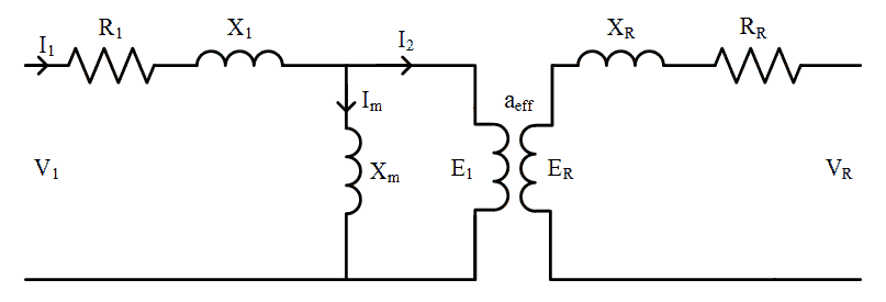
Consider the equivalent circuit of a wound rotor induction machine when the rotor circuit is not referred to the stator, shown in Fig. 3.
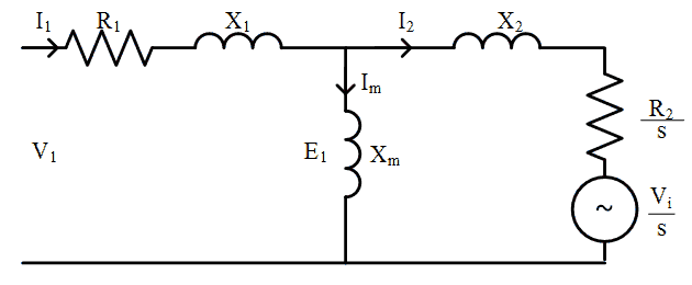
The induced rotor voltage \(E_R\) is a function of slip and the frequency of the actual rotor circuits (and magnitude of \(X_R\)) is also a function of slip, as described in the devlopment of the per-phase equivalent circuit model. However, in a wound rotor induction machine, the effective turns ratio at standstill, \(a_{eff}\) is actually known. It can be found by measuring the open circuit rotor terminal voltage when the rotor is stationary. As with the process when devloping the conventional per-phase equivalent circuit model, the rotor components may be referred to the stator (primary) side of the transformer, dividing by slip to account for the change in induced rotor voltages as speed changes, shown in Fig. 4.
The rotor terminal phase voltage, referred to the stator can be thought of as a voltage injected into the rotor circuit, and is given by:


Operating Principle and Analysis
Considering the equivalent circuit, if the injected voltage is increased, the rotor current will be reduced, resulting in a reduction in the available torque generated by the motor. If there is a load applied to the motor, the rotor will slow down, resulting in an increase in slip. Considering the circuit model using a transformer between stator and rotor, as slip increases the induced rotor voltage \(E_R\) increases and the rotor current \(I_R\) will increase. This represents what physically happens in the machine. In the circuit model with the rotor variables referred to the stator, the rotor current referred to the stator \(I_2\) increases as the effective injected voltage seen by the stator \(V_i/s\) reduces as slip increases. This process allows the machine to find a new steady state where the induced rotor current produces enough torque to equal the load torque.
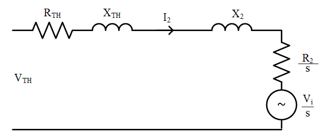
To analyse performancethe analysis, the stator phase voltage, stator impedance and magnetising reactance can be replaced by a Thevenin source and impedance, as shown in Fig. 5.

If the injected voltage is in phase with the rotor current, then the voltages in the equivalent circuit may be written as
and re-arranging:
Power and Torque
Considering the diagram above and remebering that the injected voltage is in phase with the rotor current, the air gap power of the machine, (total power flow from the stator to the rotor), may be written as:
Given that for all induction machines
the torque may be written as
The first of the two equations above gives the torque as a function of slip, rotor current and injected rotor voltage. The second equation shows that at a given torque, the rotor current \(I_2\) must be constant. In turn, this means that if the torque is constant the ratio
Finally, consider the power flow components of the airgap power. The airgap power is the sum of the power lost in the rotor circuit, the power flow out of the rotor terminal and the power converted to mechanical energy. Since the injected voltage is assumed to be in phase with the rotor current, the rotor terminal power will simply be \(3 V_i I_2\). The airgap power compoments are:
And the power converted to the mechanical system is given by
No-Load Condition
Consider again the expression for slip:
If the torque is zero, then the rotor current will also be zero. Therefore, at zero torque, the no-load slip, \(s_0\), is given by
Efficiency
Since some of the power supplied to the motor is recovered from the rotor circuit, the efficiency cannot be calculated as simply output power over stator input power. Instead, in a wound rotor machine with a variable voltage and frequency supply connected to the rotor, the efficiency is
where \(P_{stator}\) and \(P_{rotor}\) are the stator and rotor terminal power flows respectively.
Wound Rotor Induction Machine Operating Modes
As noted above, the torque may be written as:
- Sub-synchronous motoring
In this mode slip and torque are both positive, therefore injected voltage must be in phase with rotor current. Power flows into the stator and back out of the rotor circuit.
\[ s \gt 0 \mspace{24mu} \frac{V_i + I_2 R_2} {s} \gt 0 \mspace{12mu} \rightarrow \mspace{12mu} \ V_i + I_2 R_2 \gt 0 \] - Super-synchronous motoring
Above synchronous speed, the slip is negative. In order for the torque to be positive,
\[ s \lt 0 \mspace{24mu} \frac{V_i + I_2 R_2} {s} \gt 0\mspace{12mu} \rightarrow \mspace{12mu} \ V_i + I_2 R_2 \lt 0 \]Therefore, voltage and current must be out of phase with each other. Power is being injected into the rotor from the drive circuit connected to the slip rings, in addition to input power flowing into the stator
- Super-synchronous generating
If generating above synchronous speed, slip and torque are both negative, therefore
\[ s \lt 0 \mspace{24mu} \frac{V_i + I_2 R_2} {s} \lt 0\mspace{12mu} \rightarrow \mspace{12mu} \ V_i + I_2 R_2 \gt 0 \]Injected voltage is in phase with rotor current. In this case, mechanical input power is being supplied from the shaft and both the stator and rotor circuits are providing output power.
- Sub-synchronous generating
If generation below synchronous speed is required, torque must be negative whilst slip is positive. Again,
\[ s \gt 0 \mspace{24mu} \frac{V_i + I_2 R_2} {s} \lt 0\mspace{12mu} \rightarrow \mspace{12mu} \ V_i + I_2 R_2 \lt 0 \]Therefore, voltage and current must be out of phase with each other. Power is being injected into the rotor from the drive circuit connected to the slip rings.
Comment
In a modern implementation of a drive control for a wound rotor induction machine, the analysis above applies if the rotor terminal voltage is maintained in phase with the rotor current. It is also possible to control the machine operation by injecting reactive power through the rotor terminals, reducing the reactive power requirement of the stator winding. (Effectively, it is possible to use the rotor terminals to provide magnetizing current). Realization of the rotor voltage phase angle control is a relatively complex task that is beyond the scope of these notes.
Wound Rotor Induction Machines are capable of operation up to rated torque, at slips that are not close to the synchronous speed. Injecting voltage into the rotor circuit, the torque speed curve is shifted so that the no-load speed is not at synchonous speed. WRIM are capable of sub-synchonous generating and super-synchronous motoring. Used as "Doubly-Fed Induction Generators" they are used un Type 3 wind turbines, currently the most common type of wind turbine. Wound Rotor Machines are also showing potential for use in variable speed pumped hydro energy storage.