Induction Machine Construction
Stator
The stator construction of a three-phase induction machine is similar to that of a three-phase synchronous machine. A three-phase winding is placed in a number of slots in order to produce a rotating sinusoidal mmf wave. As with other ac machines, the speed of rotation of the stator magnetic field is described as the synchronous speed and is given by
Rotor
The rotor of an induction machine is different from other types of machine that we have considered so far: there is no requirement for a power source on the rotor. The rotor of an induction machine can be one of two types
- Wound Rotor
- Cage Rotor
Wound Rotor Machines
Wound-rotor induction machines have a three-phase winding, similar to the stator winding, on the rotor. The rotor is usually wye-connected with the terminals of the three rotor phases connected to slip-rings. In normal operation, the windings at the slip-rings are short-circuited to allow currents to flow. An advantage of wound rotor machines is that external circuits can be connected to the rotor, allowing external control of the machine. While all induction machines can be controlled to operate at different torques and speeds, wound rotor control is particularly attractive in some applications. Wound-rotor induction machines are usually significantly more expensive than cage rotor machines. Possible applications for wound-rotor machines include
- speed control of very large machines (multi-MW)
- reduced cost control of large machines
- doubly-fed induction generation (used in class 3 wind turbines). This is the probably the most common type of wound rotor machine
Cage Rotor Machines
Cage rotor machines (also called squirrel cage machines) are the most common type of induction motor. In a cage rotor design, there are solid conductors in slots on the rotor. The ends of the conductors are short-circuited at each end of the rotor using an "end-ring". For small-medium sized machines (up to a few hundred horsepower) the rotor conductors are cast using aluminum. This construction makes the rotor relatively cheap to produce. In larger machines, rotors are usually made by manually hammering solid copper bars into the rotor slots then manually brazing an end-ring in place. Fabricated rotor cages are significantly more expensive that cast rotor cages.
Induction machine photos
External
The photographs below show different aspects of induction machine construction. Clicking on each photo opens a larger version
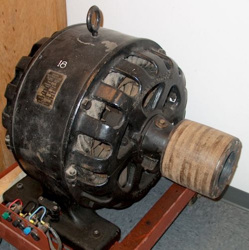
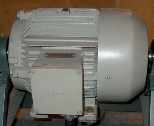
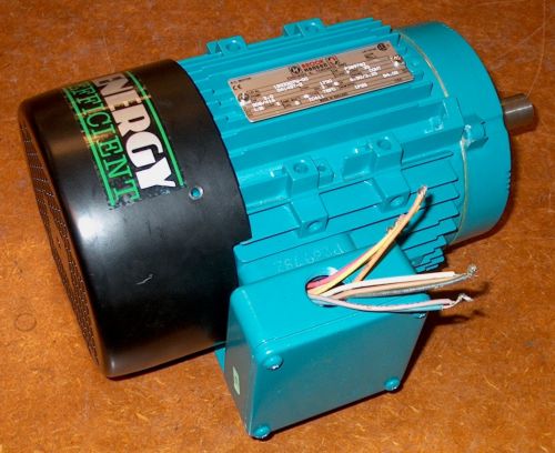
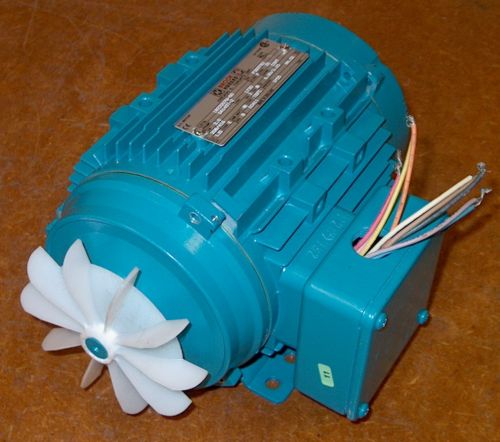
The photos in Fig. 1. show (left to right): an old 15hp induction machine, with open stator housing; a 5kW induction machine; a modern high efficiency 2hp induction machines. Both of the newer machines are of the "TEFC" type: Totally Enclosed Fan Cooled. There is no opening in the stator housing, and there is no way for environmental material (water, dirt) to get into the motor. The fan is outside the housing and blows air over the stator housing cooling fins. The 2hp motor is disassembled in Fig 2, showing the fan outside the stator housing, connected to the rotor shaft.
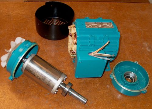
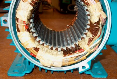
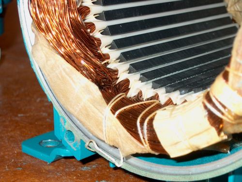
Stator
The stator of the motor is made up of many thin steel laminations stacked together and held in the rotor housing. The conductors making up the coils in the stator windings are looped through slots in the stator lamination. Coils in this machine insulated from the laminations using plastic sheets and held together with string and paper to separate coil groups. The stator coils and laminations are then dipped in varnish and baked to provide mechanical integrity.
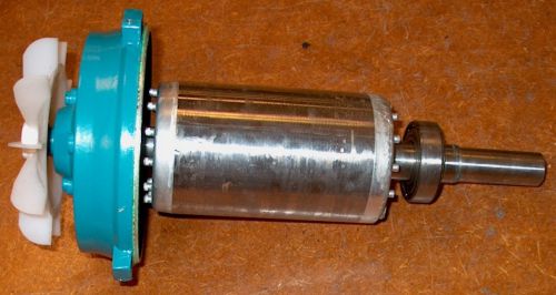
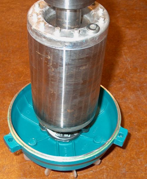
Rotor
The rotor of the 2 hp motor is constructed using steel laminationa and cast aluminum. If you look closely at the rotor photos it is possible to see where the molten aluminum has leached out between the steel laminations. In addition, the conductors in the rotor have been constructed with a "skew" of one conductor pitch. The conductors are not arranged parallel to the axis of the rotor, but at an angle, this is done to reduce torque vibrations and noise.
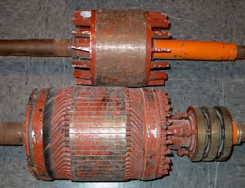
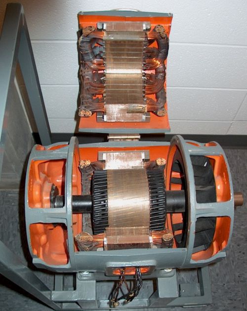
The final two photos highlight different rotor constructions. On the left are two rotors, with a cast cage rotor with large air fins to aid cooling, and a wound rotor, complete with slip rings. On the right is a cutaway motor with a fabricated cage of copper bars, also with significant skew.