Induction Machine Circuit Analysis Examples
Per Phase Equivalent Circuit
A 480V, 60 Hz, 6-pole, three-phase, delta-connected induction motor has the following parameters:
\(R_1=0.461\Omega.\), \(R_2=0.258\Omega.\), \(X_1=0.510\Omega.\), \(X_2=0.756\Omega.\), \(X_m=30.74\Omega.\)
Rotational losses are 1300W. The motor drives a mechanical load at a speed of 1170 rpm. Calculate the following information:
- Synchronous speed in rpm
- slip
- Line Current
- Input Power
- Airgap Power
- Torque Developed
- Output Power in Hp
- Efficiency
Solution
This machine has no iron loss resistance, so the equivalent circuit is as follows:
- Synchronous speed is given by:
\[ n_s=\frac{120 f}{p} = 1200\textrm{ rpm} \]
- Slip is given by
\[ s=\frac{n_s-n_m}{n_s}=\frac{1200-1170}{1200}=0.025 \]
- To calculate the line current, it is first necessary to calculate the stator phase current, which in turn requires the calculation of the phase impedance:
\[ \begin{aligned} Z_{in}&=Z_1+Z_{||} \quad Z_1=R_1+jX_1 \\ Z_{||}&=\frac{jX_m Z_2}{Z_2+jX_m} \quad Z_2= \frac{R_2}{s}+jX_2 \end{aligned} \]and \(Z_1=0.461+j0.510\Omega\), \(Z_2=10.32+j0.765\Omega\), \(Z_{||} = 8.873+j3.653\Omega \), \(Z_{in}=9.33+j4.16\Omega \). Noting that the machine is delta connected to \(V_1=V_{LL}\), the phase current is then given by\[ \begin{aligned} \vec{I}_1 &=\frac{V_1}{Z_{in}}=\frac{480}{9.33+j4.16}=42.9-j19.1A \\ I_1 & = 47.0A, I_{L}=81.3A \end{aligned} \]
- Input Power is given by \(3V_1 I_1 \cos\theta\) where \(\cos\theta =\cos\tan^{-1}\left(\frac{4.16}{9.33}\right)\). \(P_{in} = 61.8kW\)
- To find airgap power, There are two possible approaches:
- Airgap power is the input power minus stator losses. In this case the core losses are grouped with rotational loss. Therefore \(P_{gap}=P_{in}-3I_1^2R_1\), \(P_{gap}=61.8kW-3*47.0^2*0.461\), \(P_{gap}=58.7kW\).
- Airgap Power is given by
\[ P_{gap}=\frac{3I_2^2R_2}{s} \]This approach requires rotor current to be found.
- With no core loss resistance the current divider equation can be used:
\[ \vec{I}_2=\frac{jX_M}{jX_m+Z_2}\vec{I}_1 \]
- Or, the rotor current can be found from the voltage across the magnetizing branch:
\[ \vec{I}_2=\frac{\vec{E}}{Z_2} \quad \vec{E}=V_1-\vec{I}_1 Z_1 \]
- With no core loss resistance the current divider equation can be used:
- Torque can be found from \(\tau=\frac{P_{gap}}{\omega_s}\); with \(\omega_s=\frac{4 \pi f}{p}\). Substituting gives \(\tau=467Nm\).
- Output power in horsepower is the output power in Watts divided by 746. (there are 746 W in one Hp).
\[ P_{out}=P_{conv}-P_{rotational} = \tau \omega_m - P_{rotational} \]where \(\omega_m=1170\frac{\pi}{30}=122.52 rad/s\). Therefore \(P_{out}=55.95kW\), \(P_{out}=75hp\)
- Efficiency is given by \(\eta=\frac{P_{out}}{P_{in}}\) = 88.9%
Thevenin Circuit Model Analysis Example
For the machine in the previous example, find:
- Thevenin circuit parameters and Thevenin voltage
- Pullout slip
- Pullout Torque
- Start Torque
Using Matlab or Excel (or another computer program) plot the torque speed curve for slip in the range 0 to 1
- Thevenin circuit parameters and Thevenin voltage:
Thevenin circuit parameters an voltage can be found using the equations provided on the formula sheet, or from first principles. The Thevenin voltage is the voltage applied to the rotor assuming that the rotor current is zero. Thevenin impedance is the impedance of the stator part of the circuit, seen from the rotor, assuming that the stator supply is short circuited.
\[ \begin{aligned} \vec{V}_{TH} & =\frac{jX_m}{R_1+j\left(X_1+X_m\right)}\vec{V}_1 \\ V_{TH} & = |\vec{V}_{TH}| = 472.1V \end{aligned} \]\[ \begin{aligned} Z_{TH} & =\left(R_{1}+jX_1\right)|| jX_m \\ Z_{TH} & = \frac{jX_m\left(R_1+jX_1\right)}{R_1+jX_1+jX_m} \\ Z_{TH} & = R_{TH}+jX_{TH} = 0.446+j0.508 \Omega \end{aligned} \] - Pullout slip
The slip at which maximum torque occurs can be found from maximum power transfer theory. Maximum torque and maximum airgap power occur at the same slip, therefore maximum torque occurs when
\[ \begin{aligned} \frac{R_2}{s} & = \left| R_{TH}+j\left(X_{TH}+X_2\right) \right| \\ \frac{R_2}{s} & = \left| 0.446+ j1.273 \right | \\ s=\frac{0.258}{1.35}= 0.191 \end{aligned} \] - Pullout Torque
Pullout torque can be found by substituting the above pullout slip into the Thevenin torque equation
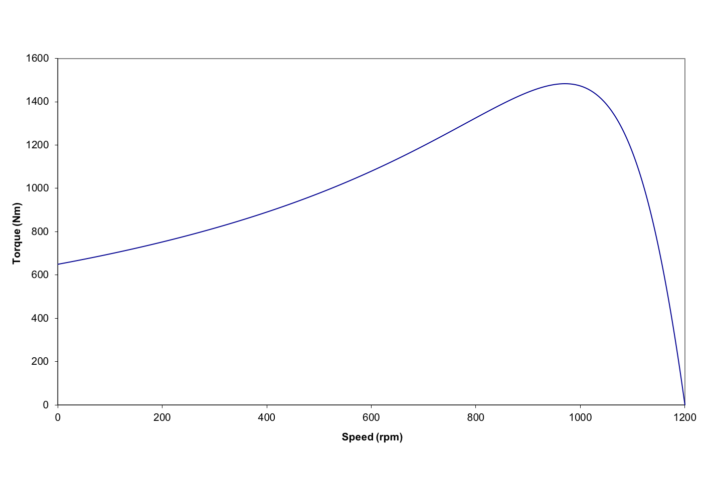
\[ \tau = \frac{3 V^2_{TH}} {\left(R_{TH}+\frac{R_2}{s}\right)^2+\left(X_{TH}+X_2\right)^2 } \frac{R_2} {s\omega_s} \]which gives \(\tau_{po}=1482Nm\)
- Start Torque. Using the same equation with s=1 gives \(\tau_{start}=649Nm\)
Using Matlab or Excel, the torque can be plotted as a function of slip using the equation in part 3: