Starting Induction Motors
Introduction
Induction Motors can usually be started by simply connecting them to the supply line voltage. This can, however, cause power system problems. Start currents (or "in-rush" currents) are high, often about 6 times rated current. Starting a motor directly from the supply line can cause the supply voltage to dip, or "sag", due to the higher than normal voltage drop across supply line and transformer impedances. In severe cases, this voltage sag can cause supply instability or the failure of sensitive power electronics connected to the system.
Wound Rotor Motors
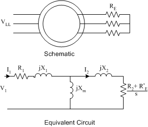
Start behaviour of wound rotor machines can be controlled by adding resistance to the rotor circuit, as shown in Fig. 1:
In the circuit model above, the actual resistance RE has been referred to the rotor as R′E. It can be seen from the circuit model that the increased impedance will reduce the start current. In addition, the extra rotor resistance will increase the motor torque during starting, reducing the start time and overall impact of the in-rush current.

Cage Rotor Machines
Cage motors cannot have additional resistance added to the rotor circuit. A number of options are available for cage motor starts:
- Full Voltage, or direct-on-line start
- Wye-Delta Start
- Adding additional circuitry to the stator, including
- Autotransformer
- Additional resistance
- Electronic soft-start or variable speed start
Full Voltage Start
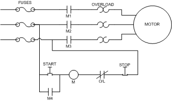
A full voltage start involves directly connecting the motor to the supply line. It can also be called a "direct-on-line" start. A wiring schematic for a full voltage start is shown in Fig. 2.
In the above circuit, the motor is protected by 3 fuses, which will have a time-delay so that inrush currents can flow for a short period. The motor is started by pressing the start button. This allows current to flow through the relay M, in turn closing the normally open relay contacts M1 to M4. Contact M1, M2 and M3 allow current to flow to the motor. M4 bypasses the start button and keeps current flowing through the relay. The motor will stop when
- The stop button is pressed, breaking the relay circuit and causing contacts M1 to M4 to open
- The thermal overload resistors heat up enough to cause the normally closed O/L contact to open, again breaking the relay circuit.
The primary advantages of the full voltage start are
- the full torque is applied to the load, causing rapid acceleration and short transient
- the start circuit is simple and low cost
The disadvantages of full voltage starting are
- rapid acceleration may be undesirable for the mechanical system
- High start currents during the transient

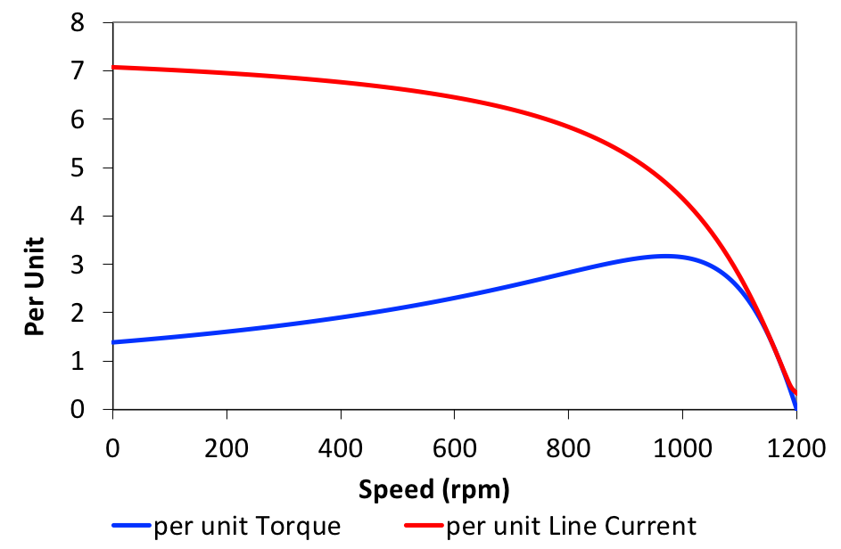
The graph in Fig. 4. plots per unit line current and torque against speed for the machine used the circuits example.
The plot shows that the line current is significantly higher than the rated current for all speeds below rated and doesn't begin to fall significantly until the slip is less than the pullout slip. It is typical for currents to remain high until rated speed is reached. A small motor should be able to start a load of rated torque in less than 10 seconds. For a larger machines, a rated load should be accelerated to rated speed in less than 15 seconds

Start Current Code Letters
In order to quantify starting currents, which can vary with machine design, all induction motors are assigned a start code letter (different from the letter used to designate the motor class). Start code letters specify the start apparent power range in terms of the rated output mechanical horsepower.
To understand how to use start codes, consider the example below:
A 480V, 50Hp induction motor has start code H. Find the maximum current
that may be expected at starting.
From the start code table, class H has a maximum start kVA of 7.1 × the rated horsepower. Therefore
Therefore the start current is
| Code Letter | Start kVA/rated Hp |
|---|---|
| A | 0 - 3.15 |
| B | 3.15 - 3.55 |
| C | 3.55 - 4.0 |
| D | 4.0 - 4.5 |
| E | 4.5 - 5.0 |
| F | 5.0 - 5.6 |
| G | 5.6 - 6.3 |
| H | 6.3 - 7.1 |
| J | 7.1 - 8.0 |
| K | 8.0 - 9.0 |
| L | 9.0 - 10.0 |
| M | 10.0 - 11.0 |
| N | 11.0 - 12.5 |
| P | 12.5 - 14.0 |
| R | 14.0 - 16.0 |
| S | 16.0 - 18.0 |
| T | 18.0 - 20.0 |
| U | 20.0 - 22.4 |
| V | 22.4 + |
Wye-Delta Start
A Y-Δ start is only applicable to motors that normally operate in delta connection and that can be re-connected to operate in wye configuration. If the motor operates in delta:
Now, if the motor is connected in wye-configuration:
Comparing the above equations, it can be seen that the wye phase current is \(\surd 3\) times smaller than the delta phase current and that the wye line current is 3 times smaller than the delta phase current.
In a wye-delta start, the motor is started in wye configuration, with line currents one third of those that would have occurred with a delta start. Once the machine has accelerated to low slip, the wye supply is removed and the motor is re-connected in delta configuration.
There are disadvantages to a wye-delta start. If the phase currents are reduced by \(1/\sqrt{3}\), the torque will also be reduced by one third. This may cause the start transient to become unacceptably long. In addition, there can be a significant short term transient when the delta connection is applied.
Additional Start Circuitry
Inrush current can also be controlled by controlling the supply to the motor.
Autotransformer Start
Using an autotransformer with a number of secondary "taps" it is possible to control the supply voltage to the motor. At low speeds, the supply voltage is kept low to maintain a low current. As slip reduces and the motor phase impedance increases, the supply voltage can be increased by changing the transformer taps. Once close to rated speed, the autotransformer can be by-passed altogether.
The autotransformer approach has the advantage that it is not necessary to access the terminals of the motor windings, the control can be applied remotely to the motor. (unlike Y-Δ). This is a significant advantage in many operating environments. However, like Y-Δ, reducing the phase supply voltage reduces the currents, torque and therefore increases the length of time of the start transient. In addition, autotransformers are expensive additional equipment that is only used in starting.
Additional Resistance or Reactance
Adding additional impedance in line with the stator increases the overall impedance of the motor circuit during starting, again limiting current at the expense of torque. Again, one of the significant disadvantages of this method is the cost of the additional equipment.
Electronic Soft Start or Variable Speed Drives
An electronic soft start works by sing power electronics to gradually increase the voltage applied to the motor. This effect is somewhat like using an autotransformer, but carried out with electronics rather than magnetic circuitry. The power electronics work similarly to a light dimmer, reducing the rms voltage, but at fixed frequency.
Variable speed drives adjust both the voltage and frequency of the supply to the motor. As a result, it is possible to accelerate a load at rated torque without exceeding rated current. Drives are generally beyond the scope of this course, but will be covered briefly.