Induction Machine Torque
Torque Equations
As with all rotating mechanical systems in steady state, torque can be found from the power and mechanical speed
In the case of an induction machine the electromagnetic torque generated by the machine, before mechanical (or rotational) losses are deducted, is defined as
Using the definitions for power converted in terms of air gap power and mechanical speed as a function of syncrhonous speed:
Substituting to write the air gap power in terms of the rotor current, the torque can now be written in terms of the rotor current and slip, giving the induction motor torque equation:
The above equation for torque in terms of rotor current and mechanical slip speed is commonly used. Electromagnetic torque developed can also be written in terms of slip frquency as:
Finally, to find the available shaft torque after rotational losses, the output power must be used.
Thevenin torque equation
Using the equation
does not give simple insight into how the torque of a machine varies with speed, as the rotor current is a function of slip. To plot a torque speed curve, we need to first solve the circuit model to find the rotor current. In the absence of a computer, this is a tedious process at best. Multiple solutions of the above equation for torque at different slips can be made simpler by simplifying the equivalent circuit model. Consider the per-phase equivalent circuit diagram in Fig. 1:
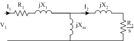
The stator part of the equivalent circuit (together with the magnetising branch) can be replaced by a Thevenin equivalent circuit. In the Thevenin circuit, the stator phase voltage has been replaced by its Thevenin equivalent,
and the impedances have been replaced by Thevenin equivalent impedances.
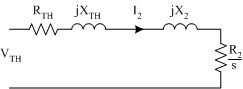
Using the circuit in Fig. 2, the calculation of rotor current is greatly simplified
The above expression for rotor current can be squared and substituted into the torque equation
Using the above equation, the variation of torque with slip can be plotted directly .
Note that if power or efficiency calculations are needed, the full equivalent circuit model should be used (not the Thevenin version).
Torque Speed Curve
General Curve
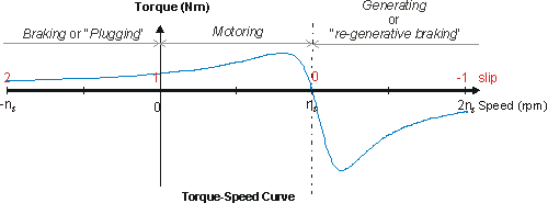
Using the Thevenin torque equation it is relatively easy to calcaulte the torque as a function of slip. This plotted is in Fig. 3 over the range of slip from +1 to -1. Remembering that \(\omega_m=(1-s)\omega_s\),a slip of +1 corresponds to a speed \(\omega_m=-\omega_s\), or \(n_m=-n_s\), and a slip of -1 corresponds to a speed of \(\omega_m=2\omega_s\), \(n_m=2n_s\).
Operating Regions
The torque-speed curve brakes down into three operating regions:
- Braking, \(n_m \lt 0\), \(s \gt 1\)
Torque is positive whilst speed is negative. Considering the power conversion equation\[ P_{conv}=(1-s)P_{gap} \]it can be seen that if the power converted is negative (from \(P=\tau \omega\) ) then the airgap power is positive. i.e. the power is flowing from the stator to the rotor and also into the rotor from the mechanical system. This operations is also called plugging.
This mode of operation can be used to quickly stop a machine. If a motor is travelling forwards it can be stopped by interchanging the connections to two of the three phases. Switching two phases has the result of changing the direction of motion of the stator magnetic field, effectively putting the machine into braking mode in the opposite direction. - Motoring, \( 0 \lt n_m \lt n_s \), \( 0 \lt s \lt 1 \)
Torque and motion are in the same direction. This is the most common mode of operation. - Generating,\(n_m \gt n_s\), \(s \lt 0\)
In this mode, again torque is positive whilst speed is negative. However, unlike plugging,\[ P_{conv}=(1-s)P_{gap} \]indicates that if the power converted is negative, so is the air gap power. In this case, power flows from the mechanical system, to the rotor circuit, then across the air gap to the stator circuit and external electrical system.
Motoring Torque Characteristic
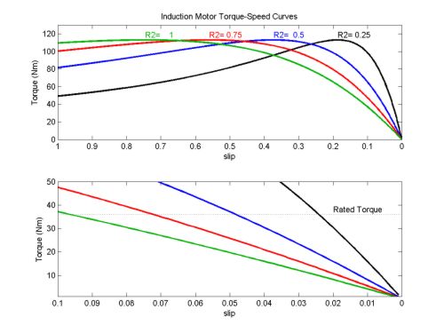
The motoring region of the induction machine torque-speed curve is the region of greatest interest. The plots below show a number of different torque speed curves, due to differences in the motor designs. Common features of interest are noted and discussed below.
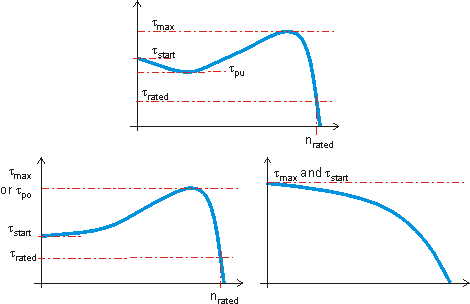
- \(\tau_{rated}\). The rated torque of the machine. This is the design operating point.
- \(\tau_{start}\). The start torque of the machine, when the machine is at standstill.
- \(\tau_{max}\), or\(\tau_{po}\). The maximum torque or pull-out torque, which occurs at the slip \(s=s_{po}\). Once a machine has reached rated operating point, this is the maximum torque that can be applied without stalling the machine (pulling out). In reality, since this torque is significantly more than the design rated torque, operation at maximum torque is not possible due to thermal heating issues. (Currents will be above rated values, \(I^2R\) losses will be excessive.)
- \(\tau_{pu}\). The pull-up torque of the machine. In some machines, the lowest point on the torque speed curve between starting and pullout is not the start torque. In this case it is important to know the pull-up torque. This is the minimum torque that the motor can accelerate up to the desired operating speed.
In steady state operation, an induction motor will operate at the speed where the mechanical load torque equals the torque developed by the motor. At low speeds, the difference between the motor torque and the load torque accelerates the machine. Normal operation is to the right of the maximum torque \(\left(s\lt s_{po}\right)\). In this region, an increase in the load torque will cause the motor to slow, increasing the motor torque until an equilibrium is reached. To the left of the pullout torque, no such equilibrium can be reached. Mechanically,
where \(J\) is the rotational inertia of the mechanical system.
Pull-out Torque
The Thevenin torque equation was used above to plot the torque-speed curve of an induction machine. Since the torque is given only as a function of slip, it is possible to use that equation to find the slip at which torque is a maximum. However, a mathematically simpler and intuitively clearer answer can be found be considering the power flow in the Thevenin equivalent of Fig. 2. Analysing the full equivalent circuit it was observed that
Therefore, since synchonous speed is constant, maximum torque occurs at the same slip as maximum airgap power. Considering the Thevenin circuit, and applying maximum power transfer theory to the ac circuit , maximum airgap power will occur
Re-arranging it is possible to obtain the pull out slip
Substituting the pullout slip into the Thevenin torque equation, and re-arranging, the pullout torque can be obtained
Discussion
From equations for pull out torque and pull out slip, it can be seen that
- The slip at which maximum torque occurs is proportional to rotor resistance
- The magnitude of the maxiumum torque is independent of rotor resistance
If all other parameters remain constant, increasing the rotor resistance will:
- Reduce the speed at which maximum toruqe occurs
- Increase the starting torque (until \(s_{po}=1\) )
- Increase slip for a given torque
- Reduce the speed for a given torque
- Increase the rotor losses at a given torque
The last point above can be shown by considering that the torque equation
is actually rotor copper loss divided by slip speed. If slip increases, losses must increase to maintain the torque.
The diagram below plots torque speed curves for a 230V, 60Hz, 6-pole, Y-connected motor with different \(R_2\) values. The following circuit parametrs are constant: \(R_1=0.50\Omega\), \(X_1=0.75\Omega\), \(X_2=0.50\Omega\), \(X_m=100\Omega\), \(f=60Hz\), \(p=6\), \(V_{LL}=230V\)