Field Winding
In large synchronous machines, the field is produced by large electromagnets placed on the rotor. The rotor construction can either be cylindrical (also called round-rotor or non-salient) or have a varying air gap length (a salient pole machine).
Salient Pole Designs
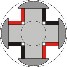
Salient pole machines are typically found in large (many MW), low mechanical speed applications, including hydrogenerators, or smaller higher speed machines (up to 1-2 MW). Salient pole machines can be constucted in pieces and then assembled later. Each pole of the machine has its own field winding which is bolted on to the rotor shaft. An illustration of a 4-pole salient pole rotor is shown below:
Each pole has a winding (which may be constructed away from the rotor), placed around a pole body, with a "pole face" bolted on top. The pole face may have a different curvature than the stator surface, making the resulting flux density more sinusoidal.
Salient pole machines are more difficult to model than round rotor machines. The torque and power characteristics are also different than those for round rotor machines. In this set of notes we only consider round rotor machines, but you should know the fundamental differences in the design of salient pole machines

Round-Rotor Machines
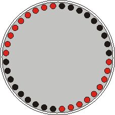
Machines with cylindrical rotors are typically found in higher speed higher power applications such as turbogenerators. Using 2 or 4 poles, these machines rotate at 3600 or 1800 rpm (with 60hz systems). Remember that machine power is a function of the size of the machine. If a high power high speed machine were to be made with salient poles, the design would cause difficulties in 2 areas: the uneven air gap length could cause unacceptable turbulence in the air gap, the centrifugal forces around the periphery of the machine make it difficult to maintain the mechanical integrity. A cylindrical design is significantly stonger and has much lower windage losses than a salient pole machine. A simplified cross-section of a cylindrical rotor is shown below.

Field Current Source
In order to produce a stationary field (with respect to the rotor) the rotor field winding must be excited using a dc current. This creates the difficulty of passing DC current to the moving rotor. There are two basic options:
- Use slip rings and carbon brushes to pass DC current to the rotor from a stationary circuit
- Use a brushless exciter. A brushless exciter creates a stationary magnetic field using a field winding similar to that in a DC machine. As conductors on the rotor pass through the stationary field, an ac voltage is induced. This ac voltage is connected to a diode rectifier mounted on the rotor and converted to dc before connection to the field winding
If slip rings and brushes are used, the open circuit voltage induced in the armature winding at a given field current should be proportional to the speed. If a brushless exciter is used, the induced voltage will be a nonlinear function of speed if the brushless exciter current is held constant.
Both of the above options need an external power source to make the generator work. One option to avoid this is to us a pilot exciter. Small permanent magnets on the shaft induce a voltage in a stationary circuit, the current in this circuit is then used to create the field in the stationary exciter.