Power Limits
There are 3 basic types of physical limit on the operation of a synchronous machine"
- Thermal
- Mechanical
- Electromagnetic
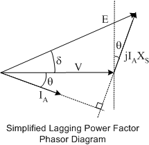
To understand the impact that the physical limits of a synchronous generator have on operation, first consider a simplified phasor diagram.
Thermal Limits
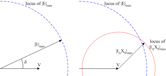
Thermal limits set the maximum temperature rise and therefore the maximum power loss in different parts of the machine. Begin by considering the rotor; the major cause of losses on the rotor is the field winding resistive loss. If the field current is above a certain level, the \(I^2R\) losses will be too high, possibly causing insulation failure in the field winding. In order to manage thermal conditions, field current is limited therefore the induced excitation in the armature winding will be limited. The rotor heating limit sets \(\left|E\right|_{max}\). Similarly on the stator, excessive armature currents will cause the stator temperature to rise beyond a safe level. The stator heating limit sets \(\left|I_A\right|_{max}\). In steady state, this limit is the rated current of the machine. (This may be exceeded by an allowed "service factor". e.g. if a machine has a rated current of 100A and a service factor of 1.15, it may safely operate continuously at 115A). The heating limits can be drawn as locii on the phasor diagram:
Mechanical and Electromagnetic Limits
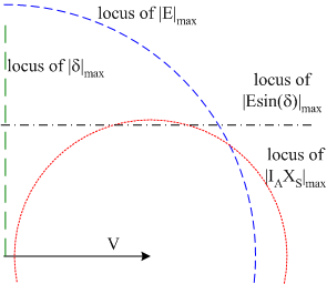
Mechanically, the input power to the generator is limited by the physical capacity of the prime mover. As a result, the prime mover limit sets the maximum output power from the generator, \(P_{max}=\left(E\sin\delta\right)_{max}\). The final limit is related to the mechanical input and the ability of the generator to electromagnetically create a torque equal and opposite to the driving mechanical torque. Recall that the torque can be thought of as the cross product of two electromagnetic fields or a function of the sine of the angle between \(V\ and \(E\) At a given excitation, if the mechanical torque increases, the rotor speeds up, increasing δ and the electromagnetic torque. This negative feedback continues until the electromagnetic and mechanical torques balance. However, if the generator is operating with δ close to 90° when the rotor speeds up, δ increases past 90°, the electromagnetic torque falls and positive feedback occurs, causing the rotor to accelerate further, pull out of synchronism and result in zero output power and possibly catastrophic failure. The static stability limit is set at \(\delta=90^{\circ}\). Adding these limits to the phasor diagram:
Power limits
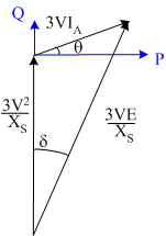
While the above phasor diagram limits can be used to describe the limits of operation of the generator, it is more useful to think in terms of limits on power, reactive power and voltamps. For this reason, the phasor diagram can be scaled by \(3V/X_S\)to obtain power and reactive power:
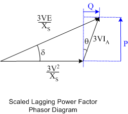
In the above diagram, positive power is on the y-axis and reactive power is on the x-axis. As it is more usual to see power on the x-axis and reactive power on the y-axis, the diagram can be re-drawn
Capability Diagram
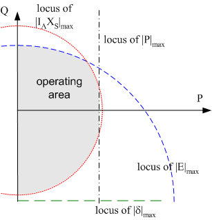
Finally, the limits from the phasor diagram can be drawn on a P-Q plot, to obtain the generator capability diagram.
Summary
The steady state limits on synchronous generator operation are:
- Rotor Heating Limit : Sets \(\left|E\right|_{max}\)
- Stator Heating Limit : Sets \(S_{max}\)and \(I_{A_{max}}\)
- Prime Mover Limit : Sets \(P_{max}\)
- Static Stability Limit: \(\delta=90^{\circ}\)