Operating a generator connected to an infinite bus
If a generator is operated off an infinite bus:
- Terminal voltage and frequency (and hence speed) are constant
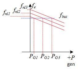
- The no-load settings of the mechanical system governor can be adjusted to supply more or less power

Fig. 1. variation of generator power with no-load set-point
Other impacts on operation can be best understood by considering the phasor diagram
To simplify analysis and aid understanding, neglect armature resistance
Since voltage is constant and assuming synchronous reactance is also constant, changing the power (with the mechanical system) will change \(E\sin\delta\) and \(|E|\) will control the reactive power. The phasor diagram is initially shown at rated operation (maximum power and apparent power). Reducing the mechanical power wihout adjusting the excitation impacts both the electrical power and reactive power.
Use the buttons below the phasor diagram to investigate the impact that changing the power and excitation have on the phasor diagram, and calculated power, reactive power and armature current.