Synchronous Motors
Introduction
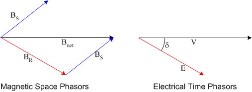
Synchronous motor construction, design and analysis is very similar to that used for synchronous generators. Insight into principles of motor operation can be found by considering the qualitative equation for torque produced by two magnetic fields:
In a generator torque opposes motion, so the rotor flux density must lead the stator flux density. In a motor, the torque is in the same direction as motion, therefore the rotor flux density must lag the stator flux density.
As in a synchronous generator, induced voltage \(\vec{E}\) is in phase with rotor flux density and terminal voltage \(\vec{V}\) in phase with net field.
In a synchronous generator, \(\vec{E}\) leads \(\vec{V}\).
In a synchronous motor, \(\vec{E}\) lags \(\vec{V}\).
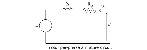
Circut
Now, consider the armature circuit of a synchronous motor. By convention, current is shown flowing into a motor and out of a generator. Since the definition of positive current flow is different from that used for synchronous generators, the armature circuit equation is also different. Summing the voltages in the armature per phase circuit diagram and phasor voltage equation.
Phasor Diagrams
Using the above equation, the phasor diagrams for various power factors can be drawn as shown below.

Power and Torque
If the armature resistance is significant, the output power and torque of a synchronous motor must be found by considering power flow in the machine:
As with synchronous generators, armature resistance can often be neglected without significant impact on analysis accuracy. In this case the simplified armature circuit equation and phasor diagrams can be used.
Using the above equation, the phasor diagrams for various power factors can be drawn as shown below.
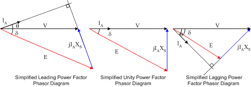
With the simplified analysis
It is important to note that while the power and torque equations are the same as for synchronous generators, the reactive power equation is different. Again, a change in signs has occurred due to the definition of positive current flow in the armature circuit.
Motor Operation
Analysis of motor operation can be carried out assuming that the motor is connected to an infinite bus: terminal voltage and frequency (hence speed) are unaffected by motor operation. It is clear from the above phasor diagrams that synchronous motors can operate with either leading or lagging power factor. This is one of the main advantages of synchronous motors. One of the primary differences between a synchronous generator and motor is that the motor operation is less affected by the mechanical system (e.g. prime mover governor, no-load, full-load frequency, prime mover limit are not applicable). Another significant difference is that while generators are often wye connected (to produce a higher line-line voltage) synchronous motors are often delta connected (reducing the armature phase current for a given power).
Since they can be operated with leading power factor, one of the primary uses of synchronous motors is in power factor correction. Power factor correction can be carried out both when the motor is supplying mechanical power and when the mechanical output is zero.
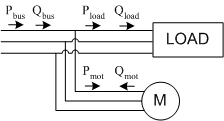
Consider the case where a synchronous motor is operated in parallel with a lagging power factor load, as shown above. Conservation of energy states that
Now, if the motor operates with leading power factor, then \(Q_{motor} \) will be negative, reducing the overall reactive power supplied from the bus. As a result, the total power factor on the bus will be greater than the power factor of the lagging load.
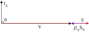
The special case where a synchronous motor is operated at zero power, but with \(E\ gt V\) is known as a synchronous condensor or synchronous capacitor. The phasor diagram for this case is shown in Fig. 5. It can be seen from the diagram that in this mode of operation, armature current leads armature terminal voltage by 90° ; the machine looks like a capacitor. Note that by reducing \(E\) the machine can also be made to look like a large inductor.
Starting
Finally, synchronous motors produce torque only at synchronous speed, which brings up the question of how to start a synchronous motor. There are two options available:
- Use a variable frequency supply to start the machine at zero frequency and slowly increase the frequency until the system frequency (e.g. 60Hz) is reached. This option is not common in large wound field machines, but is the normal mode of operation in smaller synchronous machines where the field excitation is provided by permanent magnets.
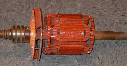
- Add an armortisseur winding. Fig. 6. shows a 6-pole synchronous machine rotor. The field winding is the oval shape around each pole. In addition to the field winding, a series of solid conductors passes through each pole. These solid conductors are short circuited at each end of the machine. This winding is called an armortisseur or damper winding. If the field winding is turned off, the armortisseur winding will act like an induction machine cage winding and provide enough torque to accelerate the motor. Once the motor reaches synchronous speed the field winding is turned on and the motor synchronizes, providing synchronous torque. (The armortisseur winding also acts to dampen speed variations due to sudden load changes. These windings are also found on synchronous generators to aid stability under transient load conditions)
Summary
Synchronous machines can operate as motors or generators. In some cases, such as pumped storage hydro schemes, they are operated as both motors and generators.
When motoring:
- \(\vec{E}\) lags \(\vec{V}\)
- \(\vec{B}_R\) lags \(\vec{B}_S\)
- Power flow is electrical to mechanical
When generating
- \(\vec{E}\) leads \(\vec{V}\)
- \(\vec{B}_R\) leads \(\vec{B}_S\)
- Power flow is mechanical to electrical.