Tests to find Circuit Parameters
Considering the armature per-phase circuit diagram, the following information is required to be able to analyze machine performance:
- Armature resistance, RA
- Voltage induced by the field winding, E
- Synchronous reactance, XS
Armature resistance is often neglected, as in large machines it is small relative to synchronous reactance. If needed, armature resistance can be obtained by a DC resistance test.
Open Circuit Voltage test
The open circuit test is carried out with the terminals of the machine disconnected from any external circuit. The basic test procedure is:
- Open circuit the generator terminals
- Drive the machine at synchronous speed using an external mechanical system
- Slowly increase the field current and measure the open circuit terminal voltage
As there is no armature current, the measured terminal voltage is the induced voltage:
If the machine is wye connected, the measure voltage will be a line-line voltage and the per-phase induced voltage can be found from
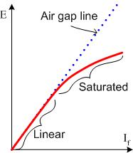
Remember from the armature winding notes that the induced voltage vs. field current plot will have a similar shape to the flux vs. field current plot.

In the plot above, the air gap line (dotted blue) gives the relationship between mmf and flux density in the air gap. (Induced voltage is proportional to flux density). At higher field current levels, the iron in the machine saturates and the percentage of field mmf applied to the air gap is reduced. As a result, the induced voltage falls below the air gap line.
As synchronous machines operate at effectively constant speed, the open circuit voltage test provides the relationship between field current and induced voltage for all load conditions. The induced open circuit voltage is sometimes known as the "excitation voltage", or even simply as the "excitation".
Short-Circuit Test
As the name suggests, the short circuit test is carried out with the terminals of the machine short circuited. The basic test procedure is as follows:
- Set the field current to zero
- Short circuit the armature terminals
- Drive the generator at synchronous speed with external mechanical system
- Slowly increase the field winding current until the short circuit armature current reaches the rated design value
Note that very low field current levels are required to achieve rated short circuit armature current
When short circuited, armature reaction prevents the machine from saturating. The short-circuit per-phase equivalent circuit and phasor diagrams are shown below.

Synchronous reactance is usually significantly larger than armature resistance. As a result, the armature current significantly lags the induced voltage. The stator flux density phasor produced by the armature current lags the armature current by 90° and consequently will lag the rotor field flux density by almost 180°.

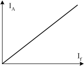
The net magnetic field, \( \vec{B}_{net} \) is too low to cause saturation and the armature current increases linearly with field current

Synchronous Reactance
As described in the armature winding notes, synchronous reactance is a combination of armature winding leakage reactance and a reactance used to represent armature reaction. The synchronous machine tests give the induced voltage and the current when armature reaction is greatest, for a range of field current values. This data can be used to approximate the synchronous reactance of the machine. It is important to note that this is only an approximation as XS is dependent on load condition and phase angle of armature current relative to the induced open circuit voltage.
In the short circuit test, the current can be calcualted as
Now, if the synchronous reactance is much larger than then armature winding resistance, \(X_S \gg R_A \), The armature reactance can be approximated as
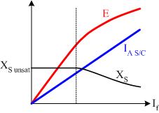
The variation of open circuit voltage, short circuit armature current and synchronous reactance is plotted below:

In the linear part of the open circuit voltage curve, the unsaturated synchronous reactance is constant. As the machine saturates, synchronous reactance falls. Synchronous reactance at a given field current (or excitation voltage) can be estimated from the gradient of the open circuit voltage and short circuit current curves.