Stand Alone Synchronous Generators
Stand alone (or off-grid) operation of a synchronous generator is in some ways the simplest form of operation. This method of operation is not as common as parallel operation of synchronous generators. Stand alone operation may typically be used in two cases:
- Emergency back-up when the power grid fails
- Remote, off-grid generation
Even in some of the above cases, a number of generators may operate in parallel. If stand alone operation is used, a generator is connected to a load and is responsible for supplying all power and reactive power required by the load.
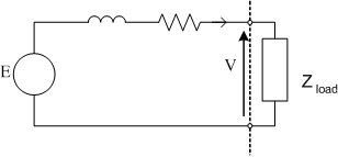
Assuming a balanced load, each supply line from the generator will carry the same current. If the generator is wye connected the per-phase circuit of the stand alone system can be thought of as a simple single phase circuit where ZLoad is the equivalent phase impedance of a wye connected load.

One must be careful when considering the per-phase circuit shown above. Remember that the terminal voltage of the generator (the voltage seen by the load) is taken as having zero phase angle. Power factor is taken from the angle between terminal voltage and current, not as you might assume from the above diagram, induced voltage and current.
Changing Load
An understanding of how load changes effect the operation of the generator can be obtained by considering the simplified phasor diagram. If we start by assuming that the generator is connected to a lagging power factor loadand the excitation of the generator is fixed, i.e. \(E\) is constant.
Using the interactive illustration, the effect of changing the magnitude of the load current at constant power factor can be clearly seen.
As current increases, \(E\sin\delta\) increases with increasing power but the terminal voltage decreases. The significant of this decrease in voltage is dependent on power factor. In simple terms, thinkng of the per-phasee circuit above, when current increases, the load impedance decreases. Thinking of the generator terminal voltage in terms of a simple voltage divider, as the load impedance falls, the proportion of the induced voltage that is dropped across the generator internal impedance increases, reducing the terminal voltage.
Now consider the case where we make the load more leading, until unity power factor load is obtaied, again with constant excitation. It can be seen that the variation in terminal voltage magnitude with current magnitude is less severe than is the case with a lagging load
Finally, we can consider the case of a leading power factor load, adjusting the current angle until it leads the induced voltage. In this special case, increasing the load current actually increases the terminal voltage, while decreasing the load reduces terminal voltage. This effect is a function of the load capacitive reactance canceling the impedance of the generator internal inductive reactance.
Phasor Diagrams for Stand-Alone Operation
It is clear from the section above that the impact of load changes on terminal voltage can be significant. Therefore, a a measure of the variation in terminal voltage with load is required. Similar to the definition used for transformers, we define voltage regulation (VR) as
where \(V_{nl}\)is the no-load voltage at the terminals of the generator and \(V_{fl}\) is the full-load voltage. The voltages in the above equation may be either phase of line-line quantities, as long as they are consistent (i.e. phase no-load and phase full-load)
In the ideal case, VR will equal 0%. However, in practiace in normal operation a required maximum value of voltage regulation must be maintained. In order to achieve this, the excitation voltage must be contunially adjusted with load conditions, i.e. the field voltage must be controlled.