Operating generators in parallel
If the power output of a generator is significant relaive to the system that it is connected to, it cannot be considered as if it is connected to a wek bus. This is the case if e.g. two generators of similar size are operated in parallel supplying a remote load. In this case, it is necessary to consider how the generators act togeher, to maintain the system frequency at the desired level.
Frequency-Power
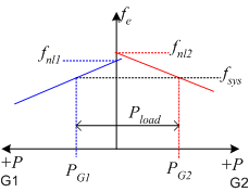
Consider the case where 2 generators are connected to supply all the power requirements for a load. In this case the frequency-power plots for both generators are drawn on the same diagram, as shown on the right. Positive power for G1 is shown on the negative x-axis, and positive power for generator 2 is shown on the positive x-axis. This type of \(f-P\) diagram is sometimes called a house diagram. The total power supplied to a load is the sum of the individual generator contributions:
Substituting to find the power from each generator in terms of the system frequency:
From the equation above it is clear that the system frequency is a function of both generator mechanical governors and no-load frequencies. In addition, the power drawn from one generator is dependent on how the other generator is operated. These changes are described and illustrated below.

f-P Diagram (House Diagram)
The diagram on the left plots the frequency-power balance for two 1.0 MW generators.
G1 has 4 poles and \(s_{p1}=5MW/Hz\). G2 has 16 poles and \(s_{p2}=4MW/Hz\)
Changing Load Power
Changes to the power drawn by the load can effect the system frequency or the generator operation. If the load is increases/decrease withour changing the no-load speeds, the system frequency will fall/rise accordingly.
Adjusting both no-load speeds
In order to compensate for variation in frequency, the generator set points can be adjusted. If both set-points are adjusted togeher, the balance of power between generators remains constant.
Adjusting only G1 or G2 no-load speed
If only one generators no-load speed is changed, the system frequency and the balance of power between the generators all change.
Voltage-Reactive Power
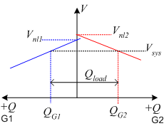
The house diagram for voltage variation with reactive power supply is constructed in a similar manner to the frequency-power diagram.
