Parallel Operation of Synchronous Generators
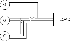
Parallel operation of generators is by far the most common form of operation. Generators may be operated in parallel on a small scale, e.g. two or three generators operating in parallel to provide power to a remote community, or large scale, e.g. the north american power grid
Benefits of parallel operation include
- Redundancy: failure of one unit does not affect the integrity of the power supply, generators may be taken out of service for preventative maintenance
- Scaling: many units can combine to provide a power demand, rather than requiring fewer very large generators
- Resource management: generators can be located and operated to best meet the generating conditions, instead of having to be located and operated to meet the requirements of a local load. An example of this may be a nuclear power plant, which may take many weeks to bring up to full operating conditions. Using a nuclear generating station at full power to meet a "base load" with smaller more rapid response generators is one way to supply fluctuating load requirements.
- Efficiency: Generators operating at full load are more efficient than those operating at low loads. It is more efficient to meet a changing load by adding or removing smaller generators than having a single large generator operating inefficiently.

Voltage and Frequency Variation
V-Q Relationship
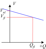
When considering synchronous generators operating alone it becomes clear that the terminal voltage of the machine is dependent on the reactive power being supplied to the load. When supplying more reactive power, the termial voltage falls. In general, the effect of changes to terminal voltage with reactive load can be plotted as shown. Increasing the inductive load on the generator reduces the terminal voltage, adding capacitance increases the terminal voltage. Reductions to the terminal voltage can be compensated by increasing the no load voltage \(E\)

f-P Relationship
The output power of a generator is largely independent of the electromagnetic generator control. The ouput power closely matches in the input power from the prime mover. The speed of rotation of the generator is also set by the prime mover, with the frequency of the open circuit induced voltage directly determined by rotational speed:
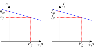
In order to understand the frequency-power relationship, it is important to try to understand the mechanical system that drives the generator. At no-load, the mechanical system is rotating at the no-load speed, \(n_{nl}\) and results in the generation of voltages at no load frequency \(n_{fl}\).
When the generator is loaded, power is drawn from the mechanical system and the generator applies a torque which opposes the direction of motion of the mechanical system. As a result, the generator tends to slow down the mechanical system. (In the same way that when you are driving on a flat road and then start to go up a hill, the car slows down).
In a synchronous generator, changing mechanical speed is undesirable, as it results in a change in the frequency of the induced voltages. For this reason, a "governor" is applied to the mechanical system to make the change in speed predictable with power changes. The mechanical governor sets the no-load speed and controls the reduction in speed so that the speed-power relationship is linear. This relationship is shown in Fig. 3. It is important to stress that this is not a function of the generator, but of how the mechanical system is controlled.

If the frequency of the generated voltages is too low, the frequency can be increased by increasing the no-load speed of the mechanical governor (equivalent to a cruise control in a car increasing the gas fed to the engine when the car goes up hill).
Mathematically, the changes in frequency with load are described using two quantities, the Speed Droop \({SD}\) and the slope of the power-frequency plot, \(S_p\) .
Speed Droop, \({SD}\) is defined as
Typical values for speed droop are in the range 2% - 4%
The power from the generator can be found using
where
The slope \(S_p\) is often quoted in kW/Hz or MW/Hz.
In the above equations, subscripts \(nl, fl \) refer to no-load and full-load operation respectively and \({sys}\) refers to the operating system frequency.
Infinite Bus
The infinite bus is a useful concept that summarizes how most people already view the power grid. It can be applied when the power grid is sufficiently large that the action of any one user or generator will not affect the operation of the power grid.
In an infinite bus:
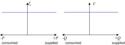
- System frequency is constant, independent of power flow
- System voltage is constant, independent of reactive power consumed or supplied
An infinite bus assumed in many small electrical applications. As an example, we take for granted that the voltage supply to a residential outlet will be 120V and 60Hz: the voltage and frequency are not changed when you turn the TV on.
Frequency-power and voltage-reactive power plots for an infinite bus are shown in Fig. 4.
